I/O Controller Hub 2
R
Intel
®
Pentium
®
4 Processor / Intel
®
850 Chipset Family Platform Design Guide 161
9.8.8 Power-Well Isolation Control
The RTC-well inputs (RSMRST#, RTCRST#, INTRUDER#) must be either pulled up to
VCCRTC or pulled down to ground while in G3 state. RTCRST# when configured as shown in
Figure 116 meets this requirement. RSMRST# should have a weak external pull-down to ground
and INTRUDER# should have a weak external pull-up to VCCRTC. This will prevent these nodes
from floating in G3, and correspondingly will prevent ICCRTC leakage that can cause excessive
coin-cell drain. The PWROK input signal should also be configured with an external weak pull-
down.
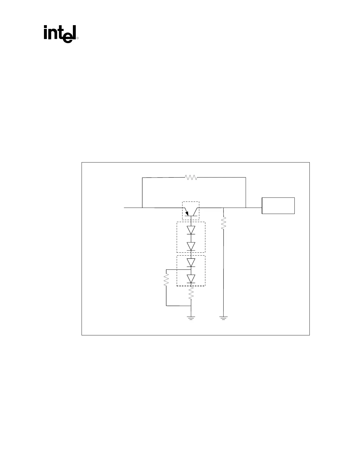
The circuit shown in Figure 116 below should be implemented to control well isolation between
the 3.3 V resume and RTC power-wells. Failure to implement this circuit may result in excessive
droop on the VCCRTC node during Sx-to-G3 power state transitions (removal of AC power).
Figure 116. RTC Power-Well Isolation Control
RSMRST#
ICH
RSMRST#
from Glue
or other
source
2.2k
10k
BAV99
iP/N 305901-001
BAV99
iP/N 305901-001
empty
MMBT3906
iP/N 101421-602
empty
RTC_PWR-Well_Isolation_Cntl
 Loading...

