Power Distribution Guidelines
R
232 Intel
®
Pentium
®
4 Processor / Intel
®
850 Chipset Family Platform Design Guide
Simulations and validations indicate that L = 3.3 nH and C
1
= 3.3 µF forms an adequate inductor-
capacitor filter. The filter must be located within 2-inches the device and the layout of VccRAC
connections should follow high-speed design practices.
In addition to the low-pass filter, the RAC requires local decoupling capacitors. These decoupling
capacitors should be located close to the RAC pins to control self-induced RAC noise. For the
inductor-capacitor filter, two to three 0.1 µF capacitors (C
2
) for both RACs should provide
adequate decoupling between VccRAC and VSS.
The inductor-capacitor filter and its associated decoupling capacitors can be implemented using
0805 size components.
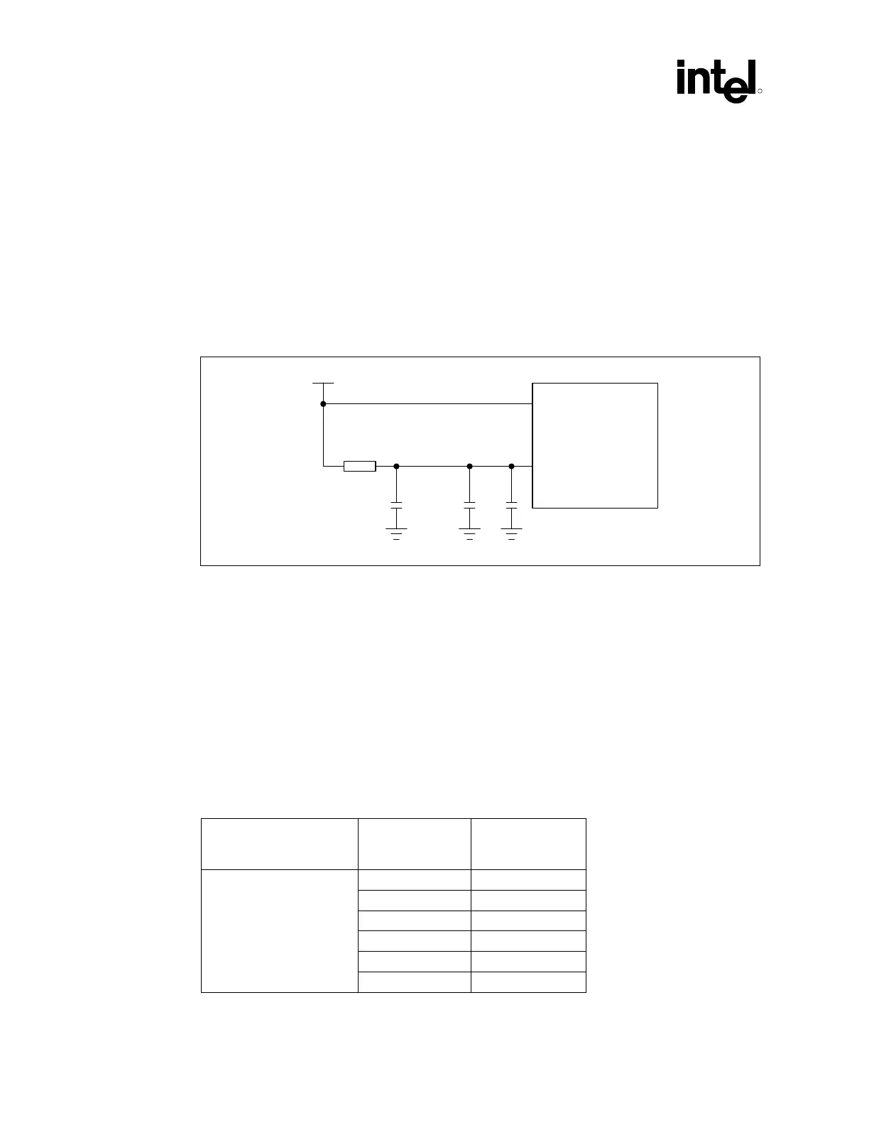
Figure 173. Ferrite Bead Filter Circuit
1.8 V
Bead
C1
C3
Vcc
Core
VccRAC
MCH
Ferrite_Bead_Filter
C2
As an alternate solution, a 10 Ω (@ 100 MHz) and 10 µF forms an adequate ferrite bead-capacitor
filter. The filter must be located within 2-inches the device and the layout of VccRAC connections
should follow high-speed design practices.
In addition to the ferrite bead filter, the RAC requires local decoupling capacitors. These
decoupling capacitors should be located close to the RAC pins to control self-induced RAC noise.
For the ferrite bead filter, use a minimum number of two 0.1 µF capacitors (C
2
) per RAC, and a
minimum of one 1.0 µF capacitor (C
3
) for both RACs should be sufficient. The layout of the
capacitor connections should follow high-speed design practices.
The ferrite bead filter and its associated decoupling capacitors can also be implemented using
0805 components except for the 10 µF capacitor, which is a 1206 size component.
Table 56. Intel
®
MCH 1.8 V RAC Pinout
Intel
®
MCH 1.8 V RAC
Pinout
Location
Channel A Channel B
T22 C16
N22 F15
J22 F14
J20 C13
R19 E9
Ball
P19 C9
 Loading...

