Schematic Review Checklist
R
244 Intel
®
Pentium
®
4 Processor / Intel
®
850 Chipset Family Platform Design Guide
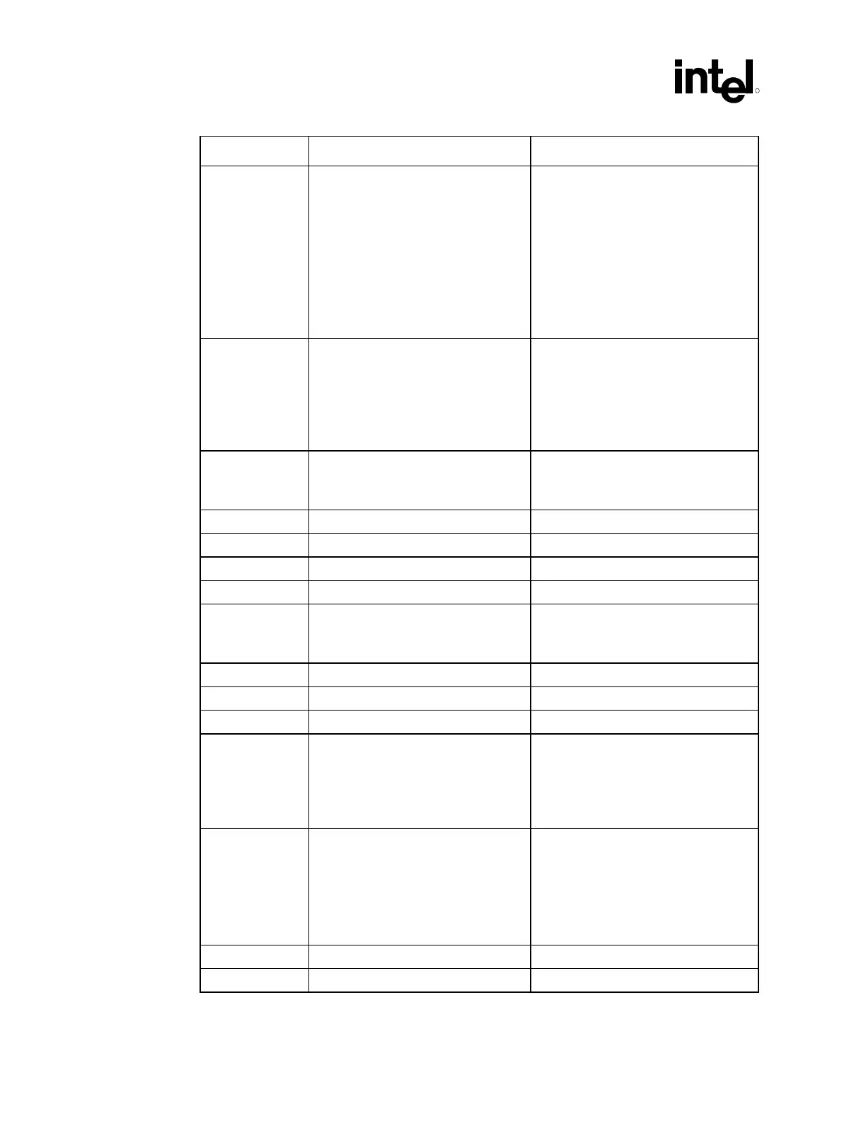
Checklist Items Recommendations Reason/Impact/Documentation
BR0# • Terminate to VCC_CPU with a 51Ω
5% resistor near the processor.
Connect to the MCH.
• The Intel 850 chipset contains on-die
termination for the BR0# signal. The
processor does not contain on-die
termination for this particular AGTL+
signal; thus, external termination is
required only on the processor end.
BR0# termination should equal the
resistance value of on die AGTL+
termination resistance (Rtt) value.
• AGTL+ common clock I/O signal
• Refer to Section 5.4.1.6.
BSEL[1:0] • Leave as no connect for 82850. Refer
to Section 4.2.1
• Connect BSEL0 to CK00 pin
SEL100/133 with a 1 k
Ω ±5% resistor
pull-up to VCC3_CLK for 82850E.
Leave BSEL1 as no connect. See
Section 4.2.2.
• 82850 – 100 MHz system bus only
• 82850E – 100 MHz or 133 MHz system
bus
COMP[1:0] • Terminate to GND with a 51.1Ω ±1%
resistor as close as possible to the
pin.
• Each COMP pin requires a separate
resistor for each pin.
• Refer to Section 5.4.1.7
D[63:0]#
• Connect to MCH • AGTL+ source synch I/O signal
DBI[3:0] • Connect to MCH • AGTL+ source synch I/O signal
DBSY# • Connect to MCH • AGTL+ common clock I/O signal
DEFER# • Connect to MCH • AGTL+ common clock input signal
DP[3:0]# • Leave as No Connect • Chipset does not support Enhanced
Data Bus Parity.
• AGTL+ common clock I/O signal
DRDY# • Connect to MCH • AGTL+ common clock I/O signal
DSTBN[3:0] • Connect to MCH • AGTL+ source synch I/O signal
DSTBP[3:0] • Connect to MCH • AGTL+ source synch I/O signal
FERR# • Terminate to VCC_CPU with a
62
Ω ±5% resistor near the processor.
• Connect to ICH2.
• This output signal is not terminated on
the processor. Termination is required
on the system board.
• Asynch GTL+ output signal
• Refer to Section 5.4.1.1.
GTLREF[3:0] • Should be set to 2/3 of VCC_CPU.
Processor should have at least 1
dedicated voltage divider for GTLREF
signals. Requires a 49.9
Ω ±1%
termination resistor to VCC_CPU and
a 100
Ω ±1% pull-down resistor to
GND as well as additional decoupling
capacitors depending on topology.
• Correct settings are critical. This signal
controls the signal reference of the
AGTL+ input pins.
• Refer to Section 5.2.
HIT# • Connect to MCH • AGTL+ Common Clock I/O Signal
HITM# • Connect to MCH • AGTL+ Common Clock I/O Signal
 Loading...

