Schematic Review Checklist
R
246 Intel
®
Pentium
®
4 Processor / Intel
®
850 Chipset Family Platform Design Guide
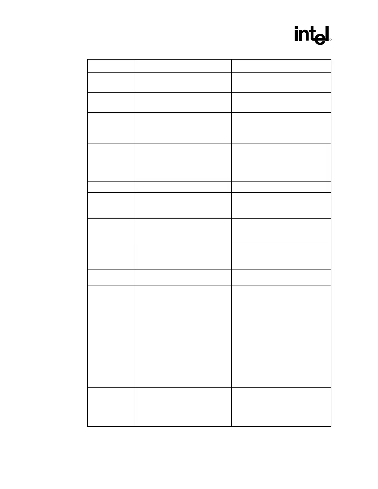
Checklist Items Recommendations Reason/Impact/Documentation
SMI# • Connect to ICH2.
• No pull-up required.
• Asynch GTL+ input signal
• Refer to Section 5.4.1.2.
STPCLK# • Connect to ICH2.
• No pull-up required.
• Asynch GTL+ input signal
• Refer to Section 5.4.1.2.
TESTHI
Refer to Section 5.4.1.11 for more
information.
• Tying any of the TESTHI pins together
will prevent the ability to perform
boundary scan testing.
• Refer to processor datasheet.
THERMTRIP# • Terminate to VCC_CPU via
62
Ω ±5% resistor.
• Voltage translation may be required if
this signal is connected to external
logic.
• Asynch GTL+ output signal
• Refer to Section 5.4.1.1.
TRDY# • Connect to MCH • AGTL+ common clock input signal
VCCA • Connect with isolated power circuitry
to VCC_CPU.
• Isolated power for internal processor
system bus PLLs.
• Refer to Section 11.4.
VCCIOPLL • Connect with isolated power circuitry
to VCC_CPU.
• Isolated power for internal processor
system bus PLLs
• Refer to Section 11.4.
VCC_SENSE • Connect to additional glue logic if
used. This signal is an output signal.
• Isolated low impedance connection to
processor core power (VCC)
• Refer to processor datasheet.
VCCVID • Connect to 1.2V linear regulator • This voltage powers the processor
dynamic VID circuitry.
VID[4:0] • Connect to VR or VRM. These are
open-drain signals from the processor
and require pull-ups to 3.3 V for
proper operation. Some VR
controllers have internal pull-ups. If
the VR controller used does not have
1 k
Ω internal pull-ups, 1 kΩ 5% pull-
ups to 3.3 V should be placed on the
motherboard.
• Refer to the Intel
®
Pentium
®
4
Processor in the 478-Pin Package VR
Down Design Guidelines.
VSSA • Connect with isolated power circuitry
to VCC_CPU.
• Isolated GND for internal PLLs
• Refer to Section 11.4.
VSS_SENSE • Connect to additional glue logic if
used. This signal is an output signal.
• Isolated low impedance connection to
core VSS.
• Refer to the processor datasheet.
TMS • Debug port signal. Refer to the latest
revision of the
Intel
®
Pentium
®
4
Processor in the 478-pin Package
Debug Port Design Guide
for
information on the connection and
termination of this signal
.
• Debug port signal. Proper termination
is required for the system to function
properly.
 Loading...

