■ Electrostatic discharge (ESD) grounding strap
CAUTION: The fan tray can be removed and replaced while the switch is operating.
However, the fan tray must be replaced within 30 seconds of removing the fan tray
to prevent the chassis from overheating.
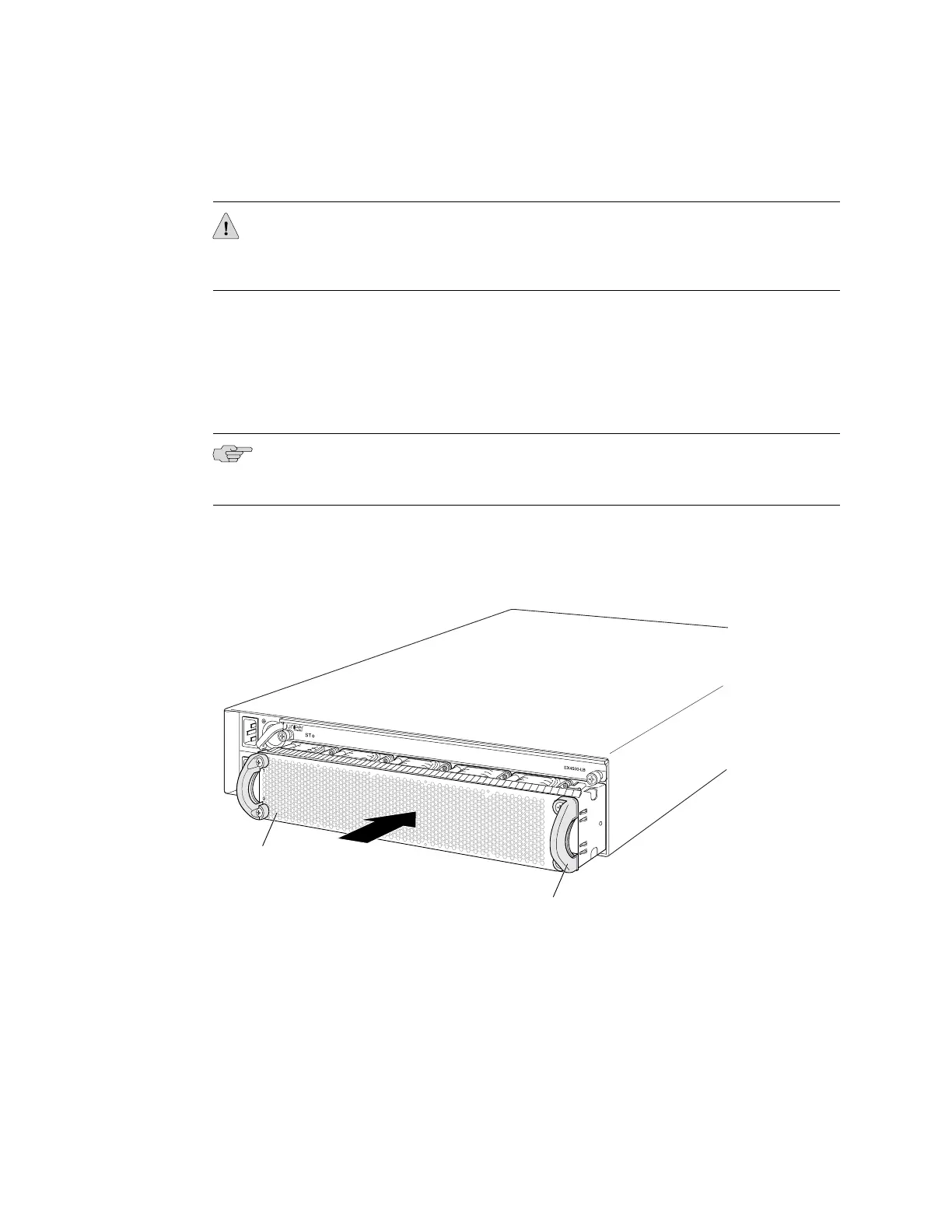
To install a fan tray in an EX4500 switch (see Figure 29 on page 76):
1. Attach the electrostatic discharge (ESD) grounding strap to your bare wrist, and
connect the strap to the ESD point on the chassis.
2. Hold the handles of the fan tray and align the tray with the fan tray guides on
the fan tray slot.
NOTE: Ensure that the power supply labels, 1 and 0, are on the left side corners of
the fan tray.
3. Slide in the fan tray until it is fully seated in the chassis.
Figure 29: Installing a Fan Tray in an EX4500 Switch
g020833
Fan tray
Fan tray handle
Related Topics Removing a Fan Tray from an EX4500 Switch on page 119■
■ Cooling System and Airflow in an EX4500 Switch on page 20
■ Field-Replaceable Units in EX4500 Switches on page 14
76 ■ Installing a Fan Tray in an EX4500 Switch
Complete Hardware Guide for EX4500 Ethernet Switches
 Loading...


