Chapter 2
Component Descriptions
■ LCD Panel in EX4500 Switches on page 9
■ Chassis Status LEDs in EX4500 Switches on page 13
■ Field-Replaceable Units in EX4500 Switches on page 14
■ Network Port and Uplink Module Port LEDs in EX4500 Switches on page 15
■ Management Port LEDs in EX4500 Switches on page 17
■ AC Power Supply in EX4500 Switches on page 18
■ AC Power Supply LEDs in EX4500 Switches on page 19
■ Cooling System and Airflow in an EX4500 Switch on page 20
■ Uplink Modules in EX4500 Switches on page 23
■ Intraconnect Module in EX4500 Switches on page 25
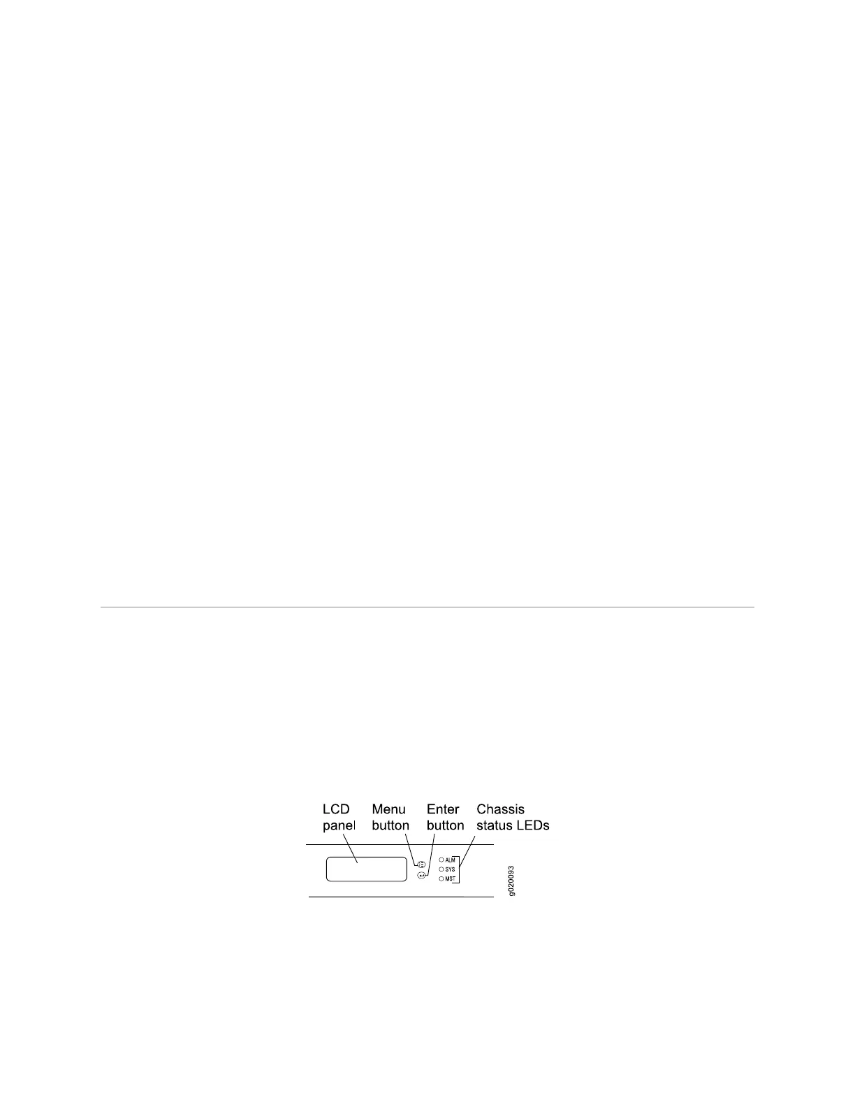
LCD Panel in EX4500 Switches
The LCD panel on the front panel of EX4500 switch shows two lines of text, each
that can contain a maximum of 16 characters. The LCD panel displays a variety of
information about the switch and also provides a menu to perform basic operations
such as initial setup and reboot.
There are two navigation buttons—Menu and Enter—to the right of the LCD panel.
See Figure 5 on page 9.
Figure 5: LCD Panel in EX4500 Switches
The first line of the text on the LCD panel displays the slot number, the role of the
switch, and the hostname. For EX4500 switches, the slot number is always 00 and
the role is always RE.
LCD Panel in EX4500 Switches ■ 9
 Loading...


