■ Network Port and Uplink Module Port LEDs in EX4500 Switches on page 15
■ Uplink Modules in EX4500 Switches on page 23
■ Optical Interface Support in EX4500 Switches on page 31
■ Installing and Removing EX4500 Switch Hardware Components on page 73
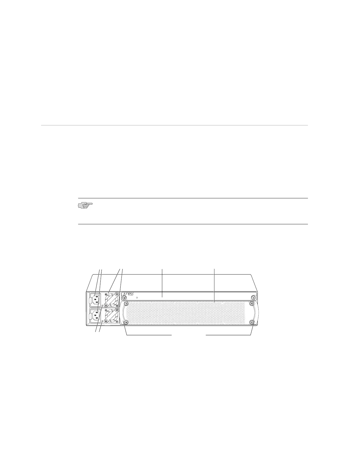
Rear Panel of an EX4500 Switch
The rear panel of the EX4500 switch consists of the following components:
■ Power supply or power supplies
■ AC appliance inlet
■ AC power supply LED
■ Fan tray
■ Intraconnect module
NOTE: The protective earthing terminal is located on the left side of the chassis. See
“Connecting Earth Ground to an EX Series Switch” on page 83.
Figure 4 on page 8 shows the rear panel of an EX4500 switch.
Figure 4: EX4500 Switch Rear Panel
g020801
EX4500-LB
ST
1
0
Fan
tray
AC power
supply LEDs
Fan tray handles
AC appliance
inlets
AC power
supplies
Intraconnect
module
Related Topics ■ Front Panel of an EX4500 Switch on page 7
■ Cooling System and Airflow in an EX4500 Switch on page 20
■ AC Power Supply in EX4500 Switches on page 18
■ Intraconnect Module in EX4500 Switches on page 25
■ Installing and Removing EX4500 Switch Hardware Components on page 73
8 ■ Rear Panel of an EX4500 Switch
Complete Hardware Guide for EX4500 Ethernet Switches
 Loading...


