To install an intraconnect module in the switch (see Figure 32 on page 80):
1. Ensure that the power is disconnected from the switch:
■ If the AC power source outlet has a power switch, set it to the OFF (0)
position.
■ If the AC power source outlet does not have a power switch, gently pull out
the male end of the power cord connected to the power source outlet.
2. Ensure that the fan tray has been removed from the switch. See “Removing a
Fan Tray from an EX4500 Switch” on page 119.
3. Attach the electrostatic discharge (ESD) grounding strap to your bare wrist, and
connect the strap to the ESD point on the chassis.
4. Taking care not to touch module components, pins, leads, or solder connections,
remove the intraconnect module from its bag.
5. Loosen the captive screws on the front faceplate of the module using the Phillips
screwdriver.
CAUTION: Before you slide the intraconnect module into the slot on the switch
chassis, ensure the module is aligned correctly. Misalignment might cause the pins
to bend, making the module unusable.
6. Using both hands, place the intraconnect module in the empty slot and slide it
in until it is fully seated.
7. Tighten the captive screws using the screwdriver.
8. Reinstall the fan tray in the switch chassis. See “Installing a Fan Tray in an
EX4500 Switch” on page 75.
9. Connect power to the switch. See “Connecting AC Power to an EX4500 Switch”
on page 89.
When the Status (ST) LED on the intraconnect module turns green, the module is
ready for use.
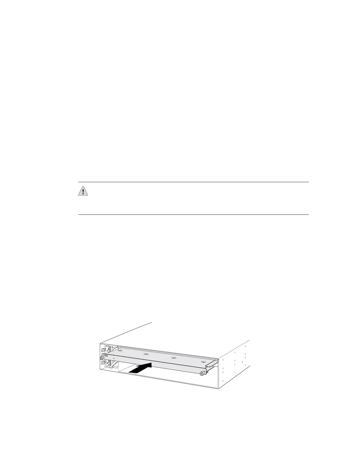
Figure 32: Installing an Intraconnect Module in an EX4500 Switch
80 ■ Installing an Intraconnect Module in an EX4500 Switch
Complete Hardware Guide for EX4500 Ethernet Switches
 Loading...


