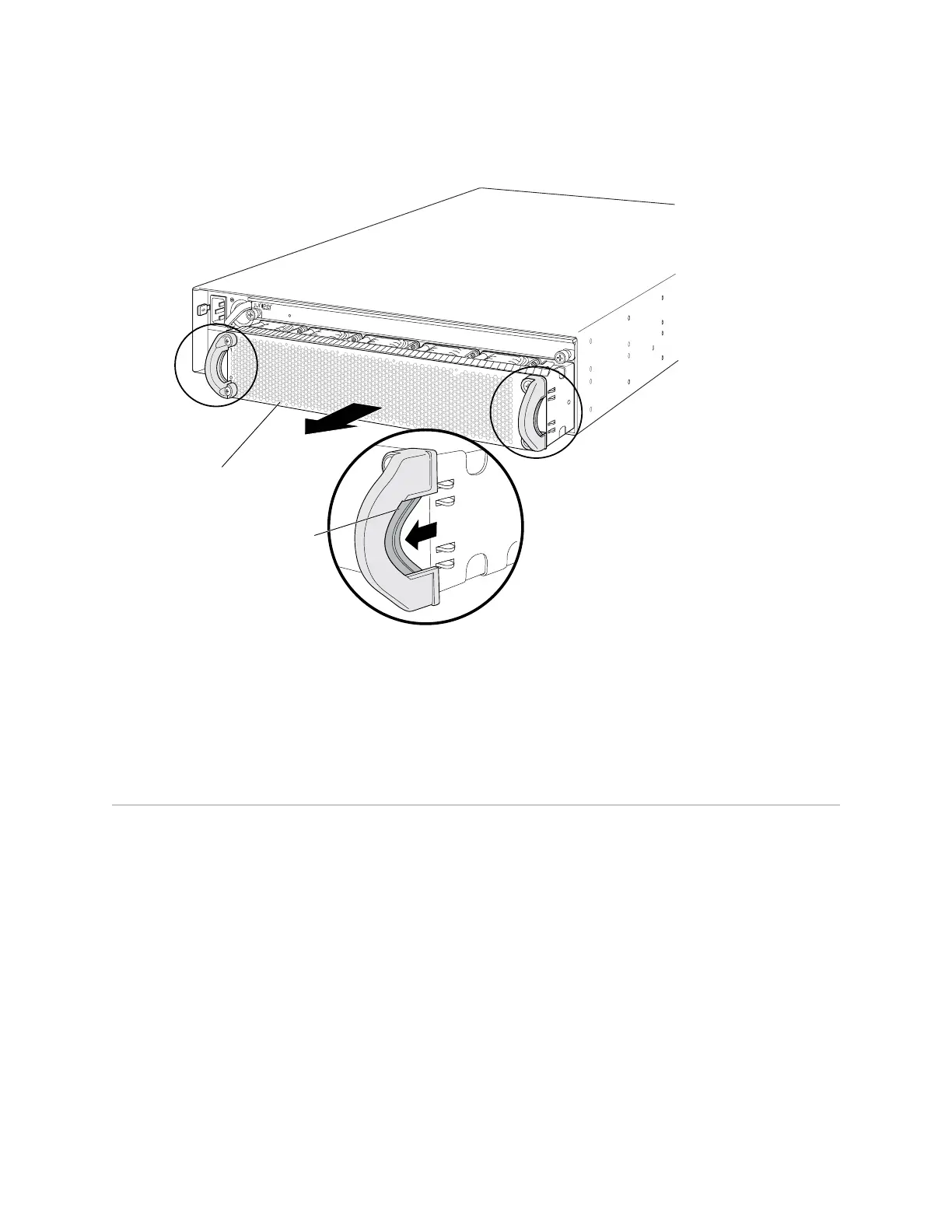
Figure 47: Removing a Fan Tray from an EX4500 Switch
g020836
Fan tray
Squeeze the handles
to release the latches
on both sides of the
fan tray.
EX4500-LB
ST
Related Topics Installing a Fan Tray in an EX4500 Switch on page 75■
■ Cooling System and Airflow in an EX4500 Switch on page 20
■ Field-Replaceable Units in EX4500 Switches on page 14
Removing an Uplink Module from an EX4500 Switch
The uplink module in EX4500 switches is a hot-removable and hot-insertable
field-replaceable unit (FRU): You can remove and replace it without powering off the
switch or disrupting switch functions.
You can install up to two SFP+ uplink modules in an EX4500 switch. Both uplink
modules install horizontally on the front of the chassis. See “Front Panel of an EX4500
Switch” on page 7.
Before you begin removing an uplink module from the switch:
■ Ensure that you have taken the necessary precautions to prevent ESD damage
(see “Prevention of Electrostatic Discharge Damage on EX Series Switches” on
page 174).
■ If there are any transceivers installed in the uplink module, remove them before
you remove the uplink module. For instructions on removing transceivers, see
“Removing a Transceiver from an EX Series Switch” on page 126.
Removing an Uplink Module from an EX4500 Switch ■ 121
Chapter 13: Removing Switch Components
 Loading...


