■ Power cords appropriate for your geographical location. See “AC Power Cord
Specifications for an EX4500 Switch” on page 57.
WARNING: Ensure that the power cords do not block access to switch components
or drape where people can trip on them.
To connect AC power to the switch:
1. Attach the electrostatic discharge (ESD) grounding strap to your bare wrist, and
connect the strap to the ESD point on the chassis.
2. Ensure that the power supply is fully inserted in the chassis. See “Installing a
Power Supply in an EX4500 Switch” on page 74.
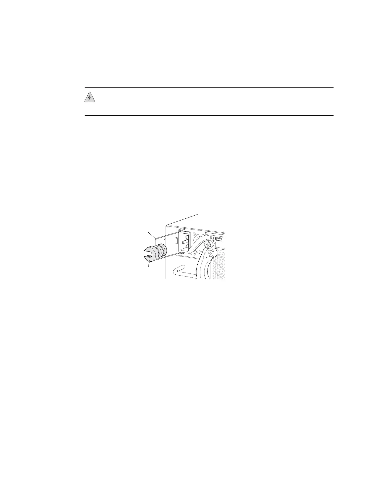
3. Squeeze the two sides of the power cord retainer clip, and insert the L-shaped
ends of the clip into the holes in the bracket on each side of the AC appliance
inlet. See Figure 36 on page 90.
Figure 36: Power Cord Retainer in an AC Power Supply
g020852
Retainer
clip
Adjustment
nut
4. Locate the power cord or cords shipped with the switch; the cords have plugs
appropriate for your geographical location.
5. Insert the coupler end of the power cord into the AC appliance inlet.
6. Push the retainer clip toward the cord until the cord slides into the slot in the
adjustment nut. Turn the nut until it is tight against the base of the coupler and
the slot in the nut is turned 90° from the top of the switch. See Figure 37 on
page 91.
7. If the AC power source outlet has a power switch, set it to the OFF (0) position.
8. Insert the power cord plug into an AC power source outlet.
9. If the AC power source outlet has a power switch, set it to the ON (|) position.
10. Verify that the LED on the power supply faceplate is lit and is on steadily.
11. Repeat steps 2 through 10 for the remaining power supplies.
90 ■ Connecting AC Power to an EX4500 Switch
Complete Hardware Guide for EX4500 Ethernet Switches
 Loading...


