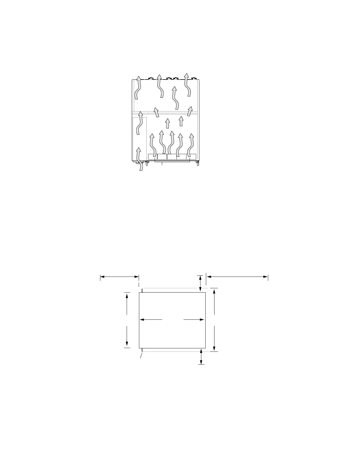
Figure 20: Back-to-Front Airflow Through the EX4500-40F-BF Switch Chassis
■ If you are mounting the switch on a rack or cabinet along with other equipment,
ensure that the exhaust from other equipment does not blow into the intake
vents of the chassis.
■ Leave at least 12 in. (30.5 cm) in front of and 24 in. (61 cm) behind the switch.
Allow at least 6 in. (15.2 cm) of clearance on each side of the chassis. Leave
adequate space at the front and back of the switch for service personnel to
remove and install hardware components. NEBS GR-63 recommends that you
allow at least 30 in. (76.2 cm) in front of the rack or cabinet and 24 in. (61 cm)
behind the rack or cabinet. See Figure 21 on page 53.
Figure 21: Clearance Requirements for Airflow and Hardware Maintenance for an
EX4500 Switch Chassis
Rear of chassis
Front of chassis
Mounting bracket
17.25"
43.8 cm
21.1"
(53.6 cm)
Clearance required
for maintenance
Clearance required
for maintenance
g020814
24" (61 cm)12" (30.5 cm)
19"
(48.2 cm)
6" (15.2 cm)
for airflow
6" (15.2 cm)
for airflow
Related Topics ■ Rack Requirements for EX4500 Switches on page 49
■ Cabinet Requirements for EX4500 Switches on page 50
■ General Site Guidelines for EX Series Switches on page 44
Clearance Requirements for Airflow and Hardware Maintenance for EX4500 Switches ■ 53
Chapter 5: Rack and Cabinet Requirements
 Loading...


