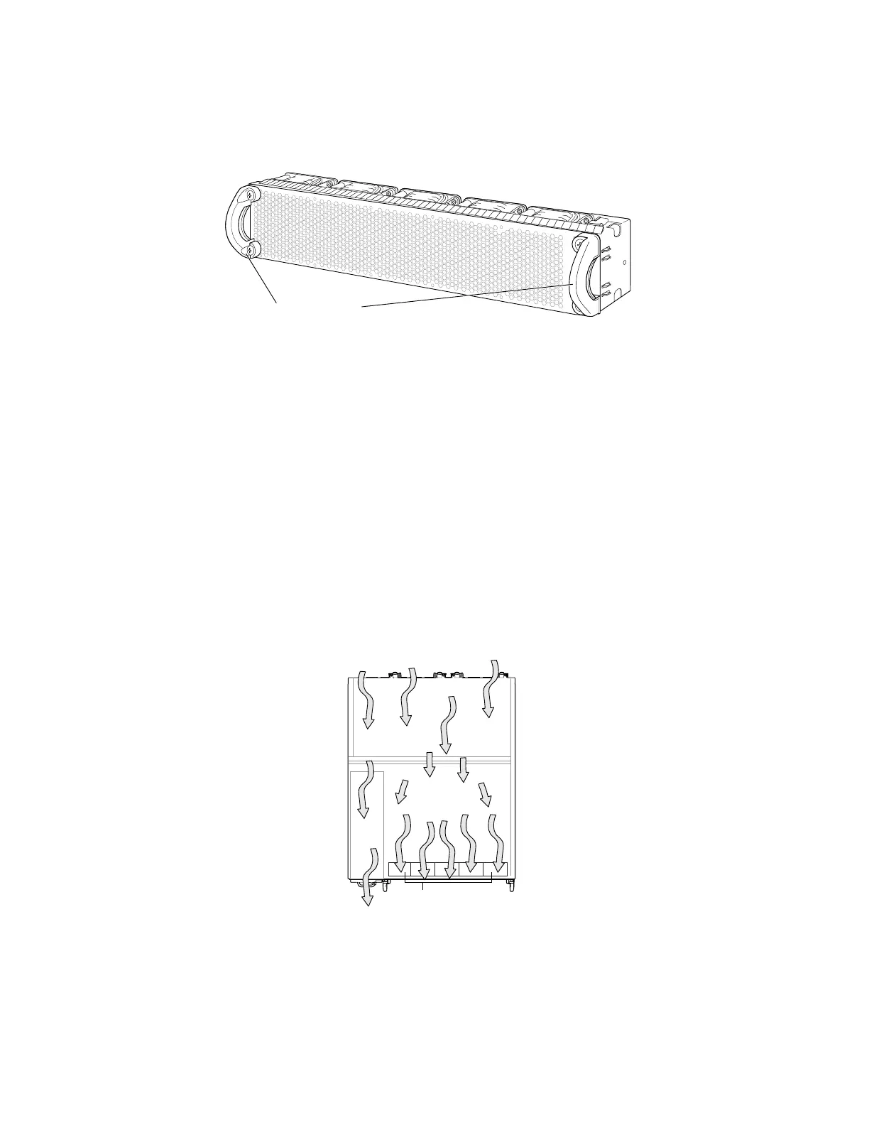
Figure 13: Fan Tray Used in an EX4500 Switch
The fan tray installs horizontally in the rear of the chassis. The fan tray has two
handles, one on each side that facilitate handling of the fan tray.
You remove and replace the fan tray from the rear of the chassis. The switch continues
to operate for a limited time (15 seconds) during the replacement of the fan tray
without thermal shutdown.
The fan tray provides front-to-back or back-to-front airflow depending on the switch
model you purchase.
In the EX4500-40F-FB model, the air intake to cool the chassis is located on the front
of the chassis. Air is pulled into the chassis and pushed toward the fan tray. Hot air
exhausts from the rear of the chassis. See Figure 14 on page 21.
Figure 14: Front-to-Back Airflow Through the EX4500-40F-FB Switch Chassis
In the EX4500-40F-BF model, the air intake to cool the chassis is located on the rear
of the chassis. Air is pulled into the chassis and pushed away from the fan tray. Hot
air exhausts from the front of the chassis. See Figure 15 on page 22.
Cooling System and Airflow in an EX4500 Switch ■ 21
Chapter 2: Component Descriptions
 Loading...


