Installing an Uplink Module in an EX4500 Switch
The uplink module in EX4500 switches is a hot-removable and hot-insertable
field-replaceable unit (FRU): You can remove and replace it without powering off the
switch or disrupting switch functions.
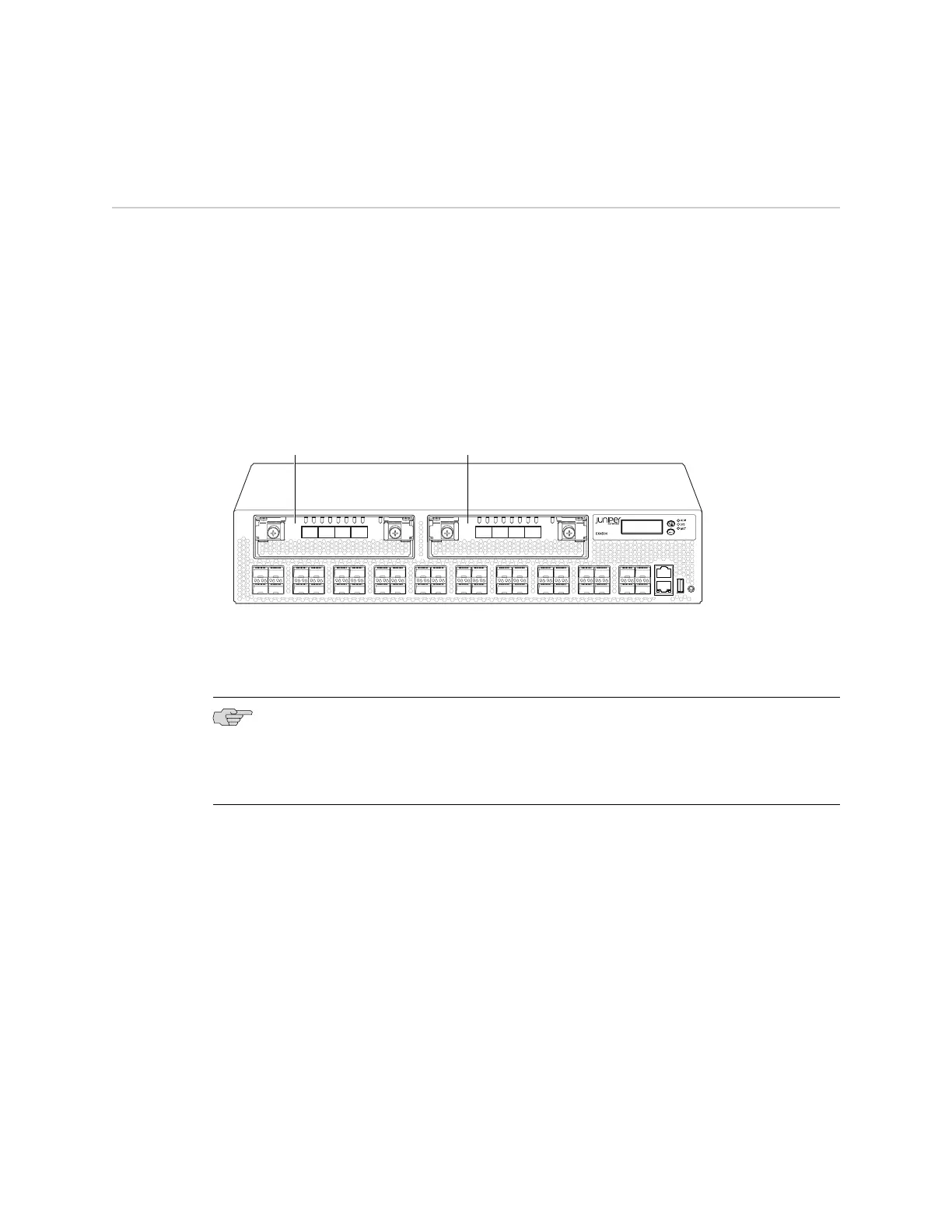
You can install up to two SFP+ uplink modules in an EX4500 switch. Both uplink
modules install horizontally on the front of the chassis. The uplink module slot on
the left is PIC 1. The uplink module slot on the right is PIC 2. See Figure 30 on
page 77.
Figure 30: Uplink Module Slots in an EX4500 Switch
g020856
0 2
1 3
0 1 2 3
ST ST
0 1 2 3
4 6
5 7
8 10
9 11
12 14
13 15
16 18
17 19
20 22
21 23
24 26
25 27
28 30
29 31
32 34
33 35
36 38
CON
MGMT
37 39
Uplink Module
(PIC 1)
Uplink Module
(PIC 2)
Each SFP+ uplink module provides four ports. Each module can house four 10-gigabit
small form-factor pluggable (SFP+) transceivers or four 1-gigabit small form-factor
pluggable (SFP) transceivers.
NOTE: When a new uplink module is installed in the switch or an existing uplink
module is replaced with another uplink module, the switch detects the newly installed
uplink module. The switch creates the required interfaces when new transceivers
are installed in those ports.
Before you begin installing an uplink module in the switch, ensure that you have
taken the necessary precautions to prevent ESD damage (see “Prevention of
Electrostatic Discharge Damage on EX Series Switches” on page 174).
Ensure that you have the following parts and tools available:
■ Electrostatic discharge (ESD) grounding strap (If a grounding strap is not available,
follow the alternative grounding method described in Step 1 of the following
procedure.)
■ Phillips (+) screwdriver, number 2
Installing an Uplink Module in an EX4500 Switch ■ 77
Chapter 9: Installing Switch Components
 Loading...


