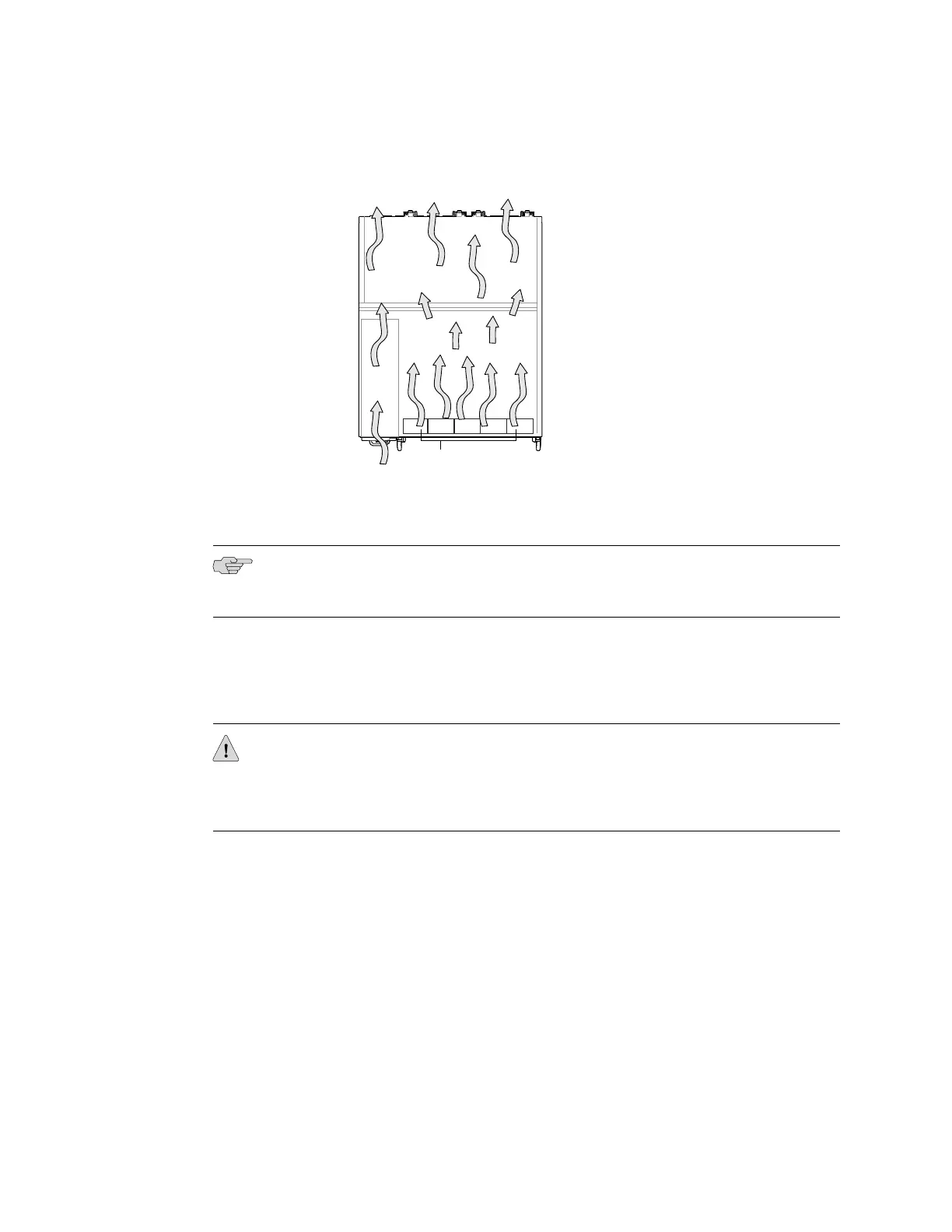
Figure 15: Back-to-Front Airflow Through the EX4500-40F-BF Switch Chassis
Each fan tray has colored intake or exhaust labels that are visible through the fan
tray vents. The intake label is orange. The exhaust label is green.
NOTE: Only one of the labels, intake or exhaust, is visible through the vents of the
installed fan tray.
The color of the label visible through the vents of the installed fan tray must match
the color of the ejector lever on the installed power supply. The color match indicates
that the power supply has the correct airflow for this model. See “AC Power Supply
in EX4500 Switches” on page 18.
CAUTION: To prevent overheating of the chassis, verify that the color of the label
visible through the vents of the installed fan tray matches the color of the ejector
lever of the installed power supply. A color match indicates that the direction of
airflow through the fan tray matches the direction of airflow of the power supply.
Temperature sensors in the chassis monitor the temperature within the chassis. The
fan tray used in the switch comes with load-sharing redundancy that can tolerate a
single fan failure at room temperature (below 113° F/45° C) to still provide sufficient
cooling.
Under normal operating conditions, the fans in the fan tray run at less than full speed.
If a fan fails or the ambient temperature rises above the threshold 113°F (45°C), the
speed of the remaining fans is automatically adjusted to keep the temperature within
the acceptable range, 32°F (0°C) through 113°F (45°C).
The system raises an alarm if the fan fails or if the ambient temperature inside the
chassis rises above the acceptable range. If the temperature inside the chassis rises
above the threshold temperature, the system shuts down automatically.
22 ■ Cooling System and Airflow in an EX4500 Switch
Complete Hardware Guide for EX4500 Ethernet Switches
 Loading...


