AC Power Supply in EX4500 Switches
The AC power supply in EX4500 switches is a hot-insertable and hot-removable
field-replaceable unit (FRU).
EX4500 switches are shipped with one power supply. A cover panel is installed in
the second power supply slot. You can add a second power supply to the switch.
Power supplies are installed at the rear of the chassis in slots labeled 1 and 0. Both
power supplies are accessible from the rear of the chassis.
WARNING: The switch is pluggable type A equipment installed in a restricted-access
location. It has a separate protective earthing terminal provided on the chassis in
addition to the grounding pin of the power supply cord. This separate protective
earthing terminal must be permanently connected to earth ground. See “Connecting
Earth Ground to an EX Series Switch” on page 83
Each AC power supply weighs approximately 3 lb (1.3 kg) and has an independent
12 A rated AC appliance inlet on its front. Each inlet requires a dedicated AC power
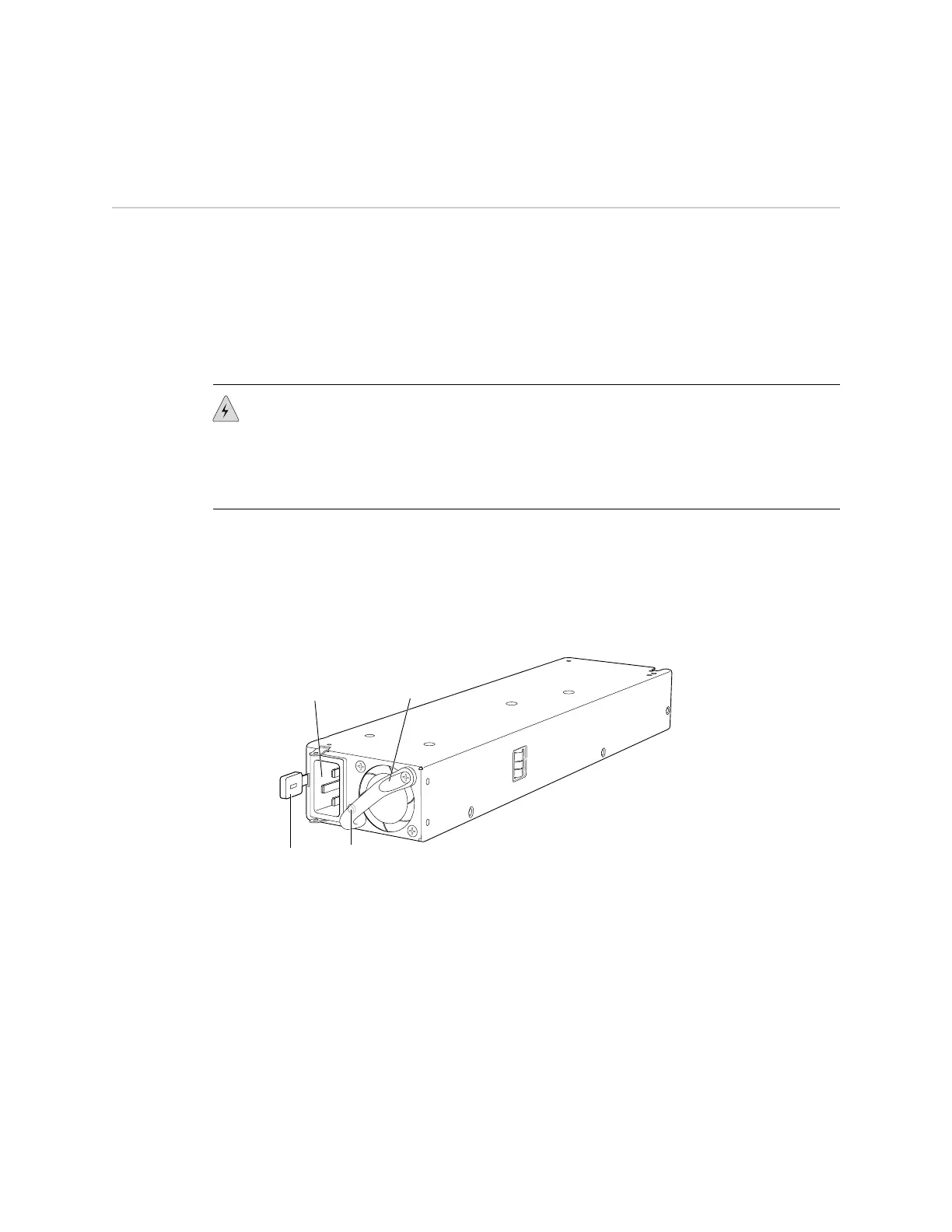
feed. Each AC power supply has a fan, a bicolor LED on the faceplate that indicates
the status of the power supply, and a colored ejector lever. See Figure 10 on page 18.
Figure 10: AC Power Supply
g020808
Ejector
lever
Power supply
LED
Power supply
handle
AC appliance
inlet
Each AC power supply has an ejector lever that holds the power supply in place. The
ejector lever locks into the corresponding hole in the chassis on the left side of the
AC appliance inlet. For instructions for installing the power supply, see “Installing a
Power Supply in an EX4500 Switch” on page 74.
Each AC power supply comes with a power cord retainer that holds the power cord
in place. See Figure 11 on page 19. The power cord retainer has a clip and an
adjustment nut. The L-shaped ends of the retainer clip hook into the bracket holes
on each side of the AC appliance inlet. The adjustment nut holds the power cord in
the correct position. For instructions for installing the power cord retainer, see
“Installing a Power Supply in an EX4500 Switch” on page 74.
18 ■ AC Power Supply in EX4500 Switches
Complete Hardware Guide for EX4500 Ethernet Switches
 Loading...


