4. Insert M4x6-mm Phillips flat-head mounting screws into the remaining four holes
in the front bracket and tighten the screws.
5. Repeat steps 2 through 4 for attaching the front bracket to the other side of the
chassis.
6. Have one person grasp both sides of the switch, lift the switch, and position it
in the rack, aligning the front bracket holes with the threaded holes in the front
post of the rack. Align the bottom hole in both the mounting brackets with a
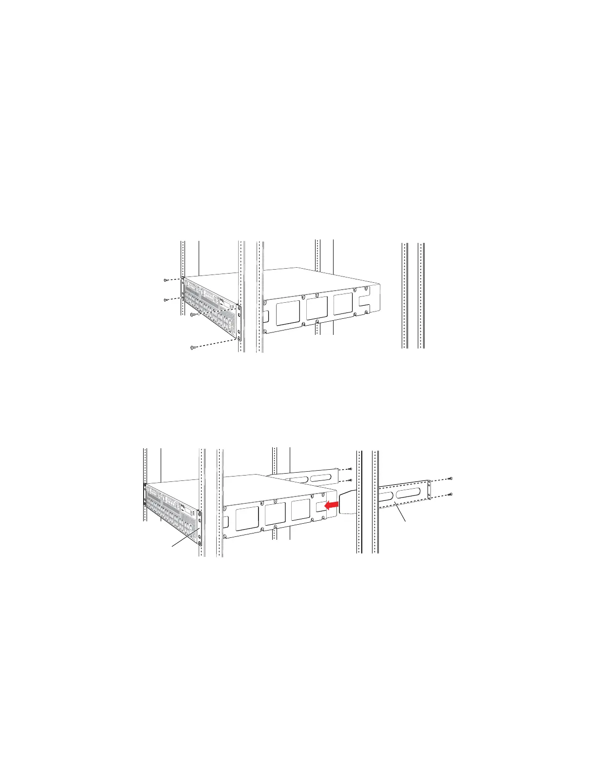
hole in each rack rail, making sure the chassis is level. See Figure 26 on page 70.
Figure 26: Mounting the Switch on the Front Posts in a Rack
7. Have a second person secure the front of the switch to the rack by using the
appropriate screws for your rack.
8. Slide the rear brackets into the front brackets. See Figure 27 on page 70.
Figure 27: Sliding the Rear Brackets to the Rear of a Four-Post Rack
g020825
Rear
bracket
Front
bracket
9. Attach the rear brackets to the rear post by using the appropriate screws for your
rack. Tighten the screws.
10. Ensure that the switch chassis is level by verifying that all the screws on the front
of the rack are aligned with the screws at the back of the rack.
Related Topics ■ Connecting Earth Ground to an EX Series Switch on page 83
■ Connecting AC Power to an EX4500 Switch on page 89
■ Connecting and Configuring an EX Series Switch (CLI Procedure) on page 107
70 ■ Mounting an EX4500 Switch on Four Posts in a Rack or Cabinet
Complete Hardware Guide for EX4500 Ethernet Switches
 Loading...


