To connect and configure the switch using the J-Web interface:
1. Transition the switch into initial setup mode:
■ EX2200 switch—Press the mode button located on the lower right corner
of the front panel for 10 seconds.
■
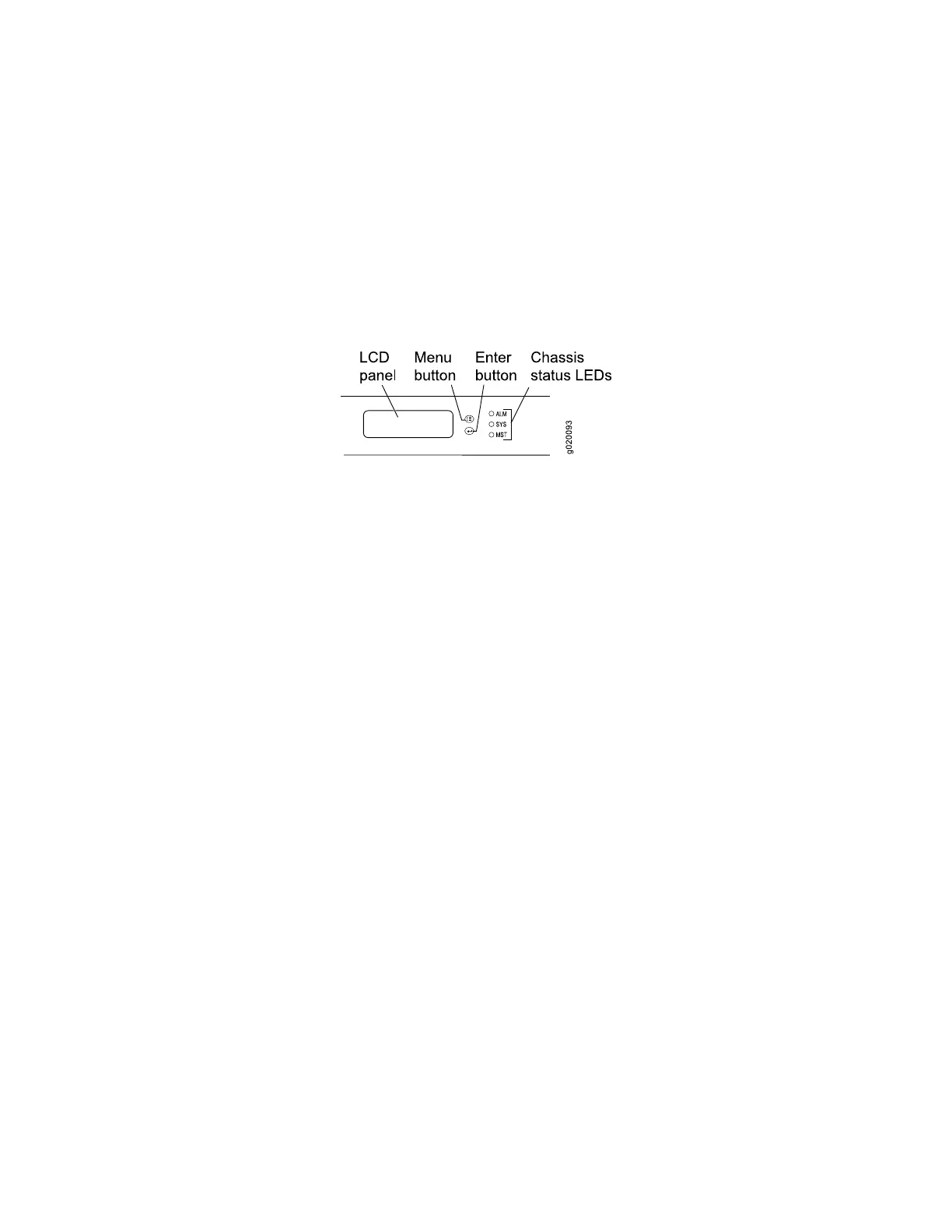
EX3200, EX4200, EX4500, or EX8200 switch—Use the Menu and Enter
buttons located to the right of the LCD panel (see Figure 45 on page 110):
Figure 45: LCD Panel in an EX3200, EX4200, EX4500, or EX8200 Switch
1.
Press the Menu button until you see MAINTENANCE MENU. Then press
the Enter button.
2.
Press Menu until you see ENTER EZSetup. Then press Enter.
If EZSetup does not appear as an option in the menu, select Factory
Default to return the switch to the factory default configuration. EZSetup
is displayed in the menu only when the switch is set to the factory default
configuration.
3.
Press Enter to confirm setup and continue with EZSetup.
2. Connect the Ethernet cable from the Ethernet port on the PC to the switch.
■
EX2200, EX3200, or EX4200 switch—Connect the cable to port 0 (ge-0/0/0)
on the front panel of the switch.
■
EX4500 switch—Connect the cable to the port labeled MGMT on the front
panel of the switch.
■
EX8200 switch—Connect the cable to the port labeled MGMT on the Switch
Fabric and Routing Engine (SRE) module in slot SRE0 in an EX8208 switch
or on the Routing Engine (RE) module in slot RE0 in an EX8216 switch.
These ports are configured as the DHCP server with the default IP address,
192.168.1.1. The switch can assign an IP address to the management PC in the
IP address range 192.168.1.2 through 192.168.1.253.
3. From the PC, open a Web browser, type http://192.168.1.1 in the address field,
and press Enter.
4. On the J-Web login page, type root as the username, leave the password field
blank, and click Login.
5. On the Introduction page, click Next.
6. On the Basic Settings page, modify the hostname, the root password, and date
and time settings:
110 ■ Connecting and Configuring an EX Series Switch (J-Web Procedure)
Complete Hardware Guide for EX4500 Ethernet Switches
 Loading...


