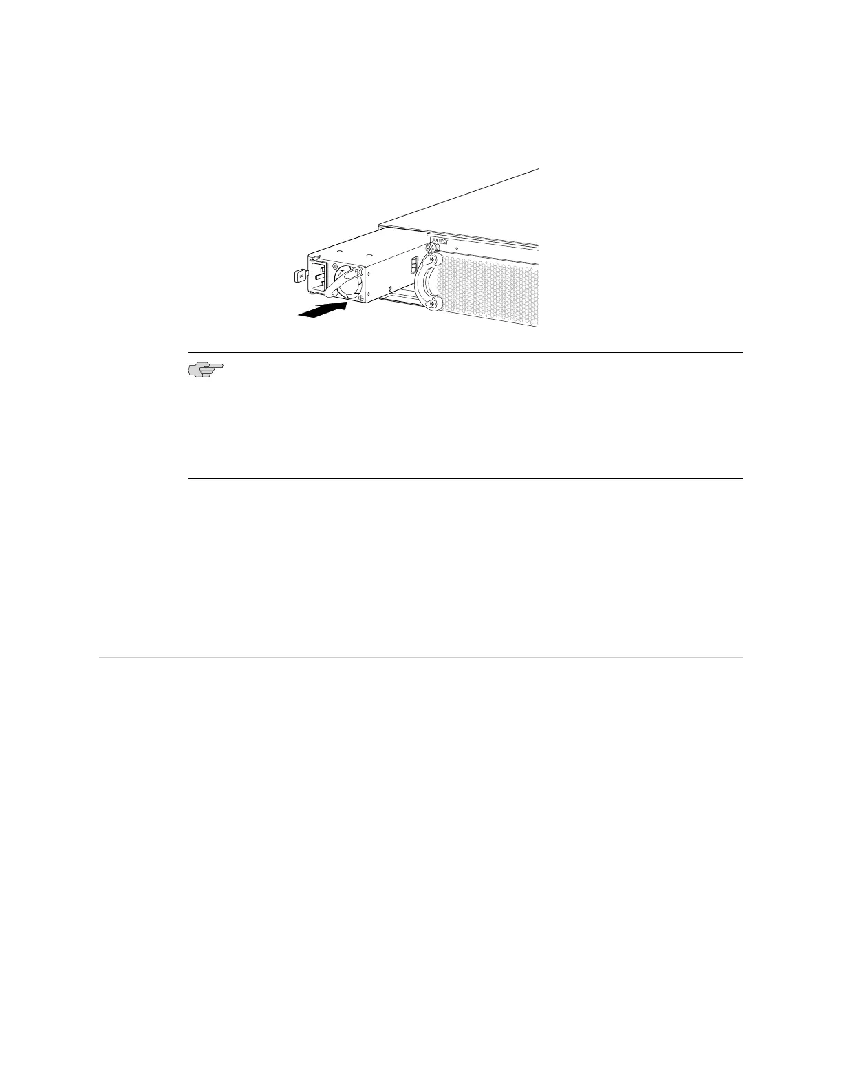
Figure 28: Installing a Power Supply in an EX4500 Switch
NOTE: If you have a Juniper J-Care service contract, register any addition, change,
or upgrade of hardware components at
https://www.juniper.net/customers/csc/management/updateinstallbase.jsp. Failure to do so
can result in significant delays if you need replacement parts. This note applies if
you change the type of power supply or add a new type of uplink module. It does
not apply if you replace these components with the same type of component.
Related Topics ■ Removing a Power Supply from an EX4500 Switch on page 118
■ AC Power Supply in EX4500 Switches on page 18
■ AC Power Cord Specifications for an EX4500 Switch on page 57
■ Rear Panel of an EX4500 Switch on page 8
Installing a Fan Tray in an EX4500 Switch
An EX4500 switch has a single fan tray. The fan tray is a hot-insertable and
hot-removable field-replaceable unit (FRU); you can remove and replace the fan tray
while the switch is running without turning off power to the switch or disrupting
switching functions.
The fan tray installs horizontally on the rear of the chassis. Handles on each side of
the front faceplate facilitate handling of the fan tray.
Before you begin to install a fan tray:
■ Ensure you understand how to prevent ESD damage. See “Prevention of
Electrostatic Discharge Damage on EX Series Switches” on page 174.
Ensure that you have the following parts and tools available to install a fan tray in
the switch:
Installing a Fan Tray in an EX4500 Switch ■ 75
Chapter 9: Installing Switch Components
 Loading...


