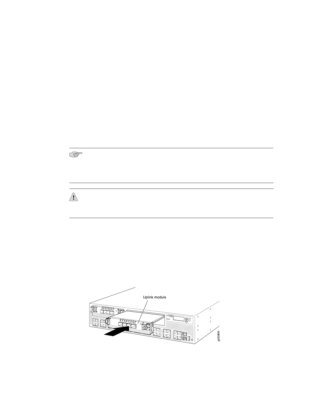
To install an uplink module in an EX4500 switch (see Figure 31 on page 78):
1. Attach the electrostatic discharge (ESD) grounding strap to your bare wrist, and
connect the strap to the ESD point on the chassis.
If a grounding strap is not available, hold the uplink module in its antistatic bag
in one hand and touch the exposed, bare metal of the switch with the other hand
to ground yourself and the component.
2. If the uplink module slot has a cover panel on it, pull one of the ejector levers
on the cover panel inward, to unseat the cover panel. Use this ejector lever to
slide the cover panel out. Save the cover panel for later use.
3. Taking care not to touch module components, pins, leads, or solder connections,
remove the uplink module from its bag.
4. Loosen the captive screws in the ejector levers using the Phillips screwdriver,
number 2. Pull the ejector levers outward until they are fully open.
NOTE: If you are removing an uplink module and installing another uplink module,
wait for at least 10 seconds after removing the uplink module before installing the
new or the same uplink module. If you do not wait for at least 10 seconds, the
interfaces on the uplink module might not come up.
CAUTION: Before you slide the uplink module into the slot on the switch chassis,
ensure the uplink module is aligned correctly. Misalignment might cause the pins to
bend, making the uplink module unusable.
5. Using both hands, place the uplink module in the empty slot and slide it in gently
until it is fully seated.
6. Push both ejector levers towards the uplink module’s faceplate to latch the module
in place.
7. Tighten the captive screws in both ejector levers using the Phillips screwdriver,
number 2. When the ST LED turns green, the uplink module is ready for use.
Figure 31: Installing an Uplink Module in an EX4500 Switch
78 ■ Installing an Uplink Module in an EX4500 Switch
Complete Hardware Guide for EX4500 Ethernet Switches
 Loading...


