NOTE: When a new uplink module is installed in the switch or an existing uplink
module is replaced with another uplink module, the switch detects the newly installed
uplink module. The switch creates the required interfaces when new transceivers
are installed in those ports.
The operating mode for an SFP+ uplink module is shown in the output of the show
chassis pic fpc-slot slot number pic-slot 1 command.
You can use the uplink module ports to connect an access switch to a distribution
switch.
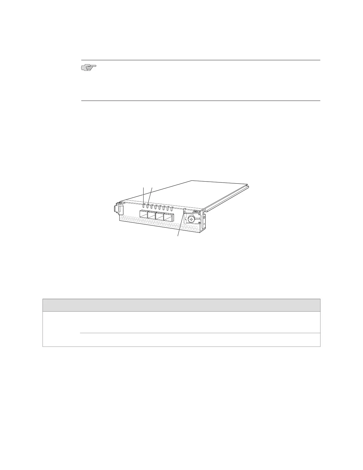
Figure 17 on page 24 shows the SFP+ uplink module.
Figure 17: SFP+ Uplink Module
g020806
0
1
2
3
ST
Link/Activity
LED
Status
LED
Status LED
The SFP+ uplink module has an LED on the faceplate (labeled ST) that indicates the
status of the uplink module. See Figure 17 on page 24.
Table 10 on page 24 describes the LED on the uplink module in an EX4500 switch.
Table 10: Uplink Module Status LED
DescriptionStateLED
■
The uplink module is offline.
■
The chassis is powered off.
UnlitST
■
The uplink module is online and functioning normally.Green
Each uplink module port has a pair of LEDs that indicate the link/activity and status
of the port. See “Network Port and Uplink Module Port LEDs in EX4500 Switches”
on page 15 for details about the uplink module port LEDs.
The SFP+ uplink modules are shipped with dust covers preinstalled in the ports.
The SFP+ uplink modules require JUNOS Software for EX Series switches, Release
9.4 or later.
24 ■ Uplink Modules in EX4500 Switches
Complete Hardware Guide for EX4500 Ethernet Switches
 Loading...


