■ Installing and Connecting an EX4500 Switch on page 63
■ Installing and Removing EX4500 Switch Hardware Components on page 73
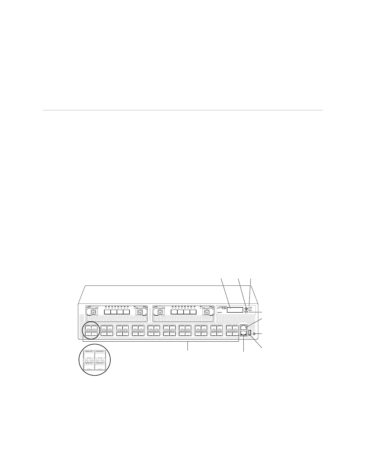
Front Panel of an EX4500 Switch
The front panel of an EX4500 switch consists of the following components:
■ 40 SFP+ network ports
■ Network port LEDs
■ Two slots for installing uplink modules—Installing the uplink modules is optional.
■ LCD panel and the LCD navigation buttons
■ Chassis status LEDs
■ Console port
■ Management port
■ Management port LEDs
■ USB port
■ ESD point
Figure 3 on page 7 shows the front panel of an EX4500 switch.
Figure 3: EX4500 Switch Front Panel
g020800
0 2
1 3
0 1 2 3
ST ST
0 1 2 3
4 6
5 7
8 10
9 11
12 14
13 15
16 18
17 19
20 22
21 23
24 26
25 27
28 30
29 31
32 34
33 35
36 38
CON
MGMT
37 39
Network ports Management port
Enter
button
Console
port
USB
port
ESD
point
LCD
panel
Chassis
status LEDs
Menu
button
0 2
1 3
Upper port numbers
Lower port numbers
0, 2, 4, 6.... 38
1, 3, 5, 7.... 39
Related Topics ■ Rear Panel of an EX4500 Switch on page 8
■ LCD Panel in EX4500 Switches on page 9
■ Chassis Status LEDs in EX4500 Switches on page 13
Front Panel of an EX4500 Switch ■ 7
Chapter 1: EX4500 Switch Overview
 Loading...


