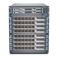
MX10008 Cooling System and Airflow
IN THIS SECTION
Fan Trays | 45
Fan Tray Controller | 48
Airflow Direction in the MX10008 Router | 51
The cooling system in an MX10008 chassis consists of two fan trays and two fan tray controllers, which
are hot-insertable and hot-removable field replaceable units (FRUs).
There are two cooling system configurations available:
•
JNP10008-FAN and JNP10008-FAN-CTRL—Designed to support the standard or enhanced power bus
and power supplies JNP10K-PWR-AC and JNP10K-PWR-DC
•
JNP10008-FAN2 and JNP10008-FTC2—Designed to support both the standard or enhanced power
bus and all power supplies
WARNING: Use only the fan tray designed for the matching fan tray controller.
To determine which chassis you have, see “MX10008 Status Panel LEDs” on page 39.
Fan Trays
Each fan tray contains internal fans, a non-removable control board, and LEDs.
The two fan trays install vertically, side by side, next to the power supplies on the FRU side of the chassis.
Two handles on each front faceplate facilitate handling of the fan tray. See Figure 19 on page 46 and
Figure 20 on page 47.
45

 Loading...