GROVE 6-77
TMS9000-2 OPERATOR MANUAL SET-UP AND INSTALLATION
Published 02-21-2019, Control # 611-05
7. Reinstall the 35 ft (10.5 m) or 58 ft (17.7 m) extension
onto the insert.
8. Refer to Insert Electrical Connection and Connecting the
Folding Extension Electrical Circuit, page 6-78 to
connect the electrical connections.
9. Refer to Connecting Main Boom Hydraulics, page 6-79
and Connecting the Folding Extension Hydraulics, page
6-79 to connect the hydraulic lines.
Removal
1. With the 35 ft (10.5 m) or 58 ft (17.7 m) extension
already removed.
2. Use another crane or suitable lifting device to remove
the insert.
3. Connect a sling to the two lifting lugs (1) (Figure 6-155)
and lift the insert enough to take the load off the
connecting pins.
4. Verify the electrical and hydraulic connections have
been disconnected. Refer to Extension Hydraulic
Connection, page 6-79 and Disconnecting Main Boom
Electrical Connection, page 6-78.
5. Remove the pins from the connecting points (1)
(Figure 6-156).
6. Insert the pins into the holders and secure them with
retaining clips.
7. Remove the insert.
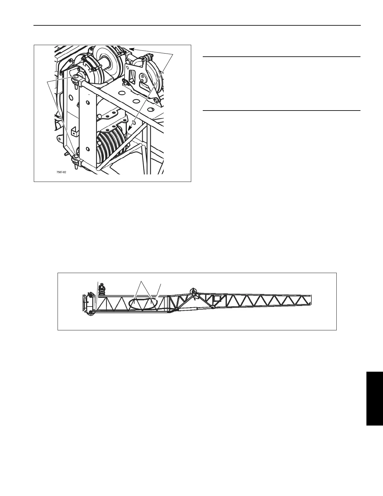
Insert Electrical Connection
The electric cable (1) (Figure 6-157) is installed in the 26 ft (8
m) insert (2), with the long end of the cable wound on the
stowage lugs (3).
When the 105 ft (32 m) boom insert is rigged, the cable is
routed through the 20 ft (6 m) insert (4).
Connecting the 26 ft (8 m) Insert to the Main Boom
Establishing a Connection
CAUTION
Equipment Damage Hazard!
Before removing an extension, ensure that the electrical
and hydraulic connections have been disconnected and
properly stowed to prevent damaging the cable and
hydraulic hoses.
7567-56
1
3
2
2
1
85 ft (26 m) Boom Insert
FIGURE 6-157

 Loading...


