Squeegee System 155Service Manual – SC6500
™
Squeegee System
Functional Description
Overview
The squeegee system includes the squeegee tool and the squeegee lift actuator.
The squeegee tool picks up the wastewater from the oor. The recovery system vacuum lifts the wastewater
from the squeegee and directs it to the recovery tank.
The squeegee lift actuator, controlled by the A2 control board assembly, raises and lowers the squeegee tool.
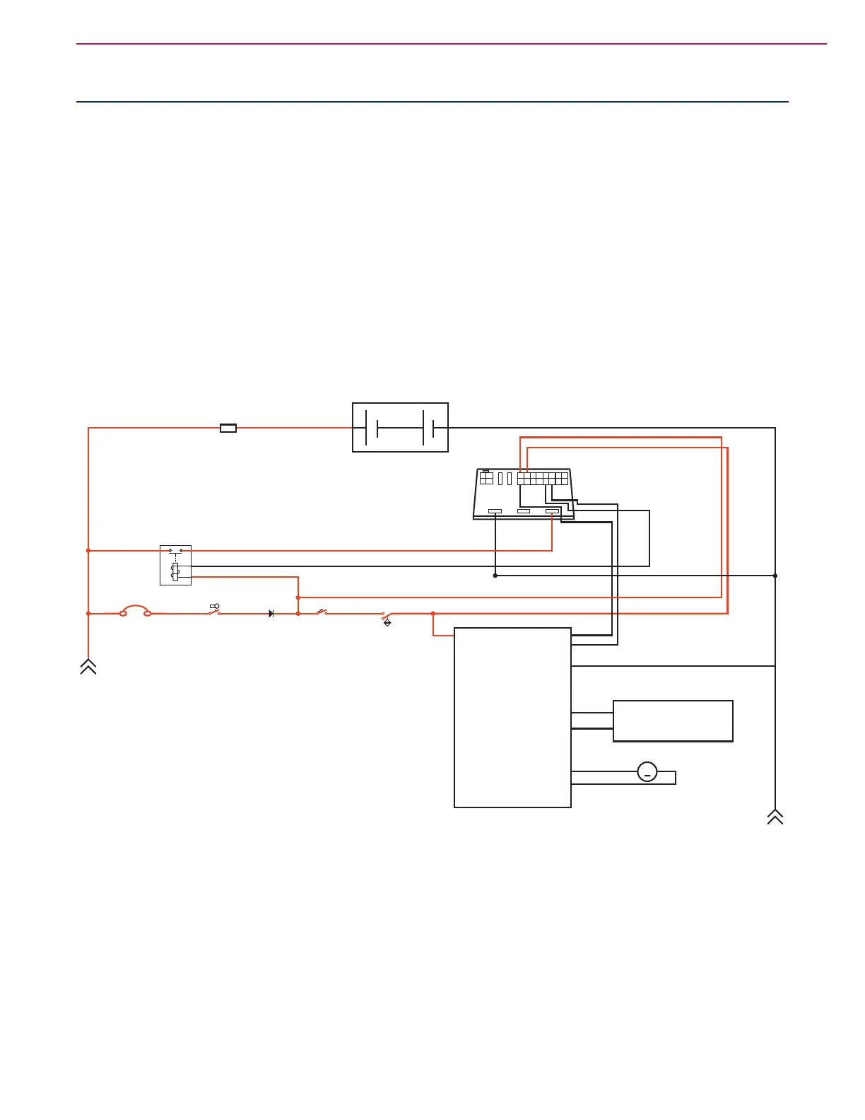
Squeegee System Wiring Diagram
Circuit Description
The Squeegee Actuator M3 gets voltage from the A2 Control Board Assembly which switches the polarity to
move the squeegee tool up or down. When the A2 Control Board Assembly receives a signal from the A3 Switch/
Display Panel Assembly
via the CAN BUS that the operator has pressed the scrub on switch, the A2 Control
Board Assembly
sends the appropriate voltage to the Squeegee Actuator M3 to lower the squeegee to the
operating position.
A2 Control
Board
Assembly
A3
Switch/Display
Panel Assembly
Fuse, 250 A
36V Battery
A1
Speed
Controller
Motion
8
B-
B+
F4
K7
F1
S1
S2
S3
D1
Key Switch Seat Switch
Battery Interlock Switch
(for roll-out Battery)
Diode
Circuit Breaker, 3 Amp
4
3
16
15
Direction
Battery Ground
CAN H
CAN L
B+
B-
+
-
M3
Squeegee Actuator
M

 Loading...