Recovery System 91Service Manual – SC6500
™
Float Cage and Ball
A shutoff Float Cage and Ball prevent the Recovery Tank from being overlled and stops any water from being
sucked into the Vacuum Motor. When the Float Ball rises (to full-tank level) it will seat itself inside the Cage
assembly and block off the Vacuum Motor airow. This causes a reduced Vacuum Motor current load which is
sensed by the A2 control board which automatically shuts off the vacuum and scrub systems.
The LCD will then display the recovery tank full indicator
icon to alert the operator that the recovery tank needs to
be drained.
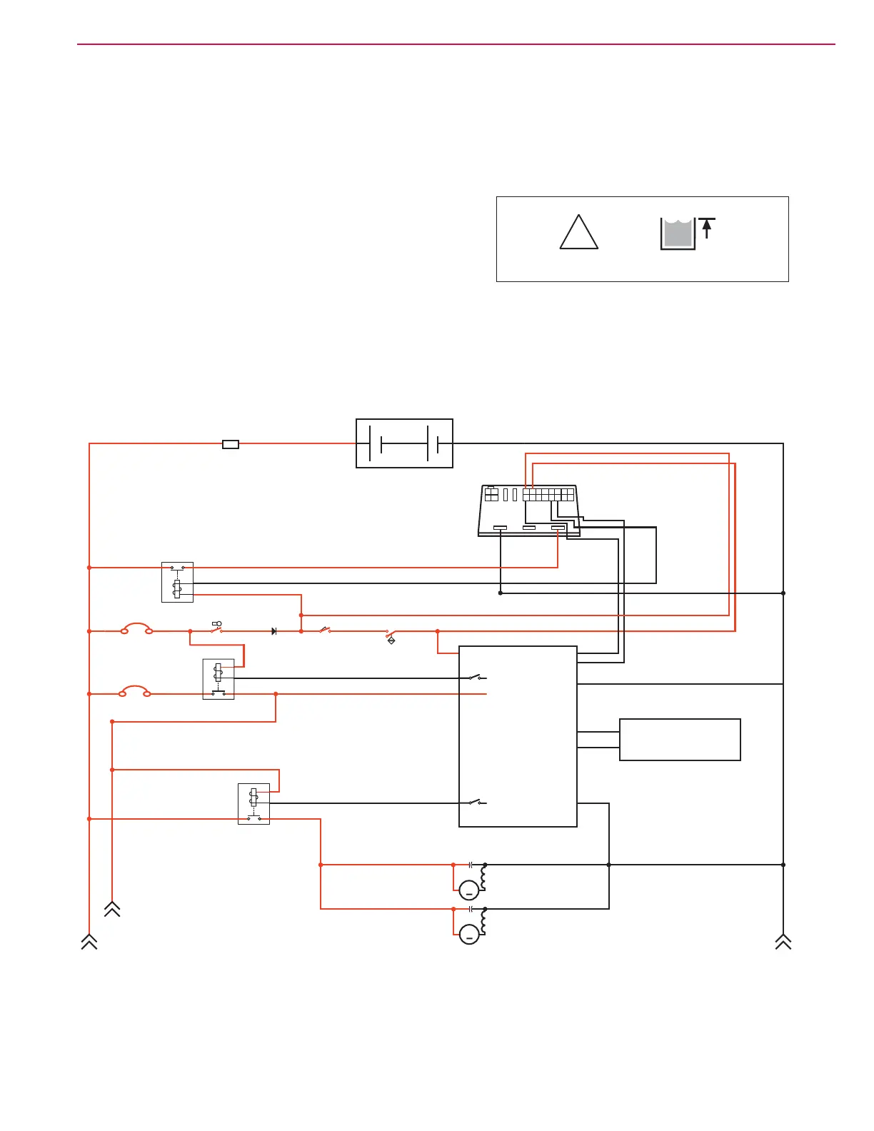
Recovery System Wiring Diagram
!
A2 Control
Board
Assembly
A3
Switch/Display
Panel Assembly
Fuse, 250 A
36V Battery
A1
Speed
Controller
Motion
8
B-
B+
F4
K7
F1
S1
S2
S3
D1
Key Switch Seat Switch
Battery Interlock Switch
(for roll-out Battery)
Diode
F2
Circuit Breaker, 15 Amp
Circuit Breaker, 3 Amp
K5
4
3
16
15
Direction
Battery Ground
CAN H
CAN L
B+
B+
B-
Bat -
Vacuum
Motor Shunt
Bat -
Bat +
+
-
K1
Vacuum Motor
M5
M
Vacuum Motor
M6
M

 Loading...