Electrical System 61Service Manual – SC6500
™
Component Locations
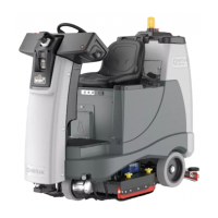
• F1 Circuit Breaker, 3 Amp (Control Circuit)
• F2 Circuit Breaker, 15 Amp (Auxiliary Circuit)
• F3 Circuit Breaker, 20 Amp (Side Brooms)
• F4 Fuse, 250 Amp
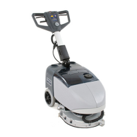
• H1 Backup Alarm (optional)
• H2 Strobe Light (optional) Not shown
• H3 Headlight (optional) Not shown
• H4 Horn - Inboard of solution lter
• K1 Contactor, Vacuum
• K2 Contactor, Right Brush (all models)
• K3 Contactor, Center Brush (45”/48” disk and all
cyl.)
• K4 Contactor, Left Brush (45”/48” disk only)
• K5 Contactor, Auxiliary
• K6 Contactor, Side Brooms
• K7 Contactor, Main (Speed Controller)
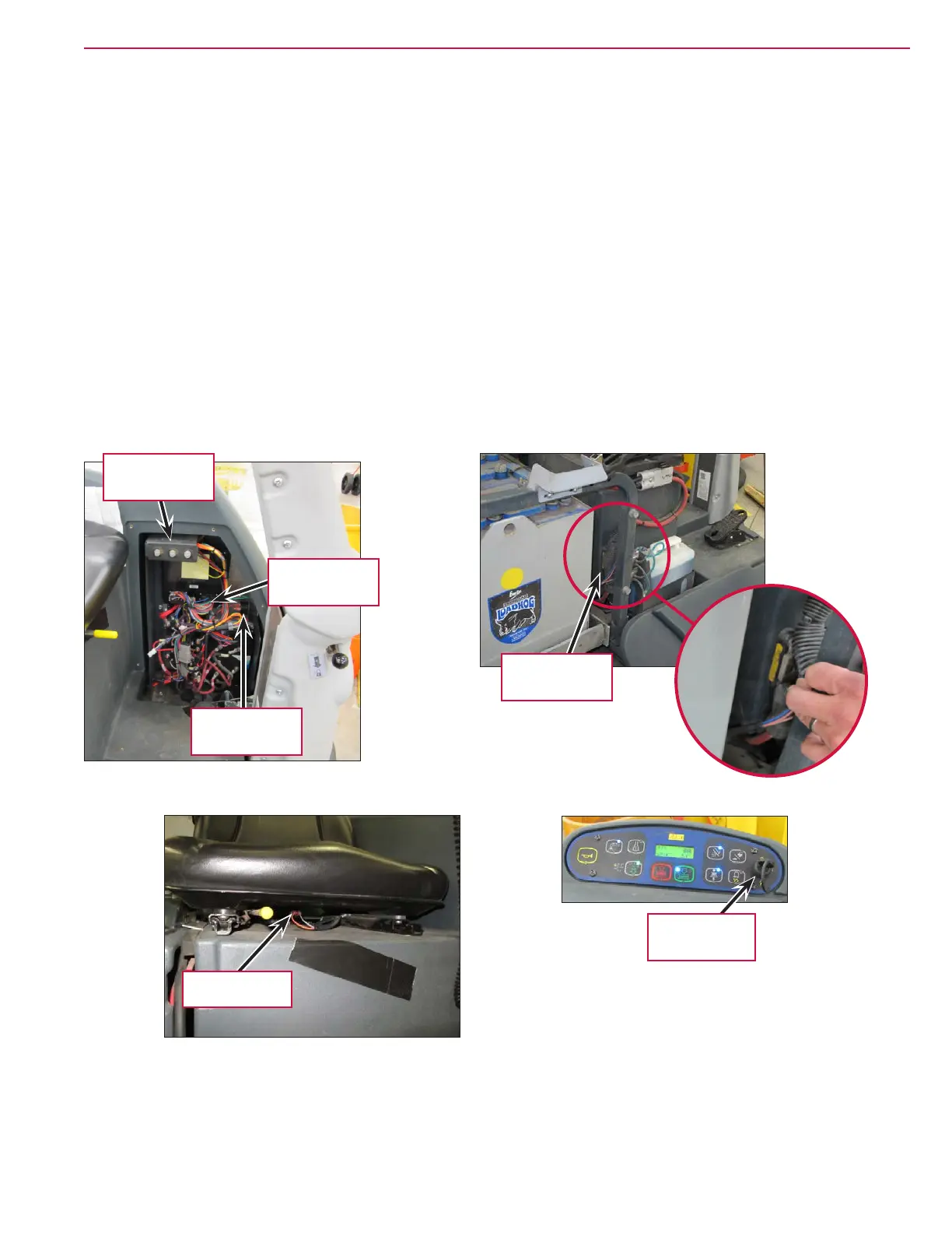
• S1 Switch, Key
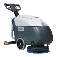
• S2 Switch, Seat
• S3 Switch, Battery Interlock (with battery roll out
option)
F4 250 Amp
Fuse
Circuit Breakers
H1 Backup
Alarm
K5 Auxiliary
Contactor
S1 Key Switch
Seat Switch

 Loading...