Sweep System, Side Broom 167Service Manual – SC6500
™
Circuit Description
The coil side of contactor K6 gets positive voltage from the Battery when the load side of contactor K5 is
closed. Contactor K5 closes when the A2 Control Board Assembly connects the K5 coil to battery ground.
Contactor K6 is connected to battery ground through the A2 Control Board Assembly.
The Side Broom Motors M7 and M8 get positive voltage from the Battery when the load side of contactor K6 is
closed. Contactor K6 closes when the A2 Control Board Assembly connects the K6 coil to battery ground. The
Side Broom Motors M7 and M8 are connected directly to battery ground.
The Side Broom Actuator M4 gets voltage from the A2 Control Board Assembly which switches the polarity to
move the side brooms up or down. When the A2 Control Board Assembly receives a signal from the A3 Switch/
Display Panel Assembly
via the CAN BUS that the operator has pressed the scrub on switch, the A2 Control
Board Assembly
sends the appropriate voltage to the Side Broom Actuator M4 to lower the side brooms to the
operating position.
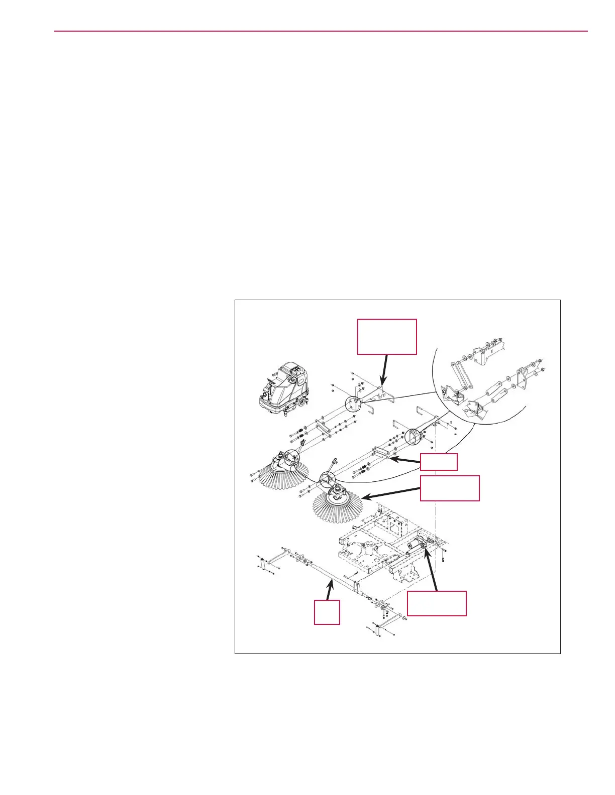
Component Locations
The Side Broom Assemblies are
mounted onto the Side Broom
Bracket Weldments
using parallel
Links, sleeve bearings, bushings
and fasteners.
The Side Broom Lift Actuator is
mounted horizontally is attached
to the machine frame and Lift Arm
with clevis pins. The Lift Arm is
connected via short chains to the
Side Broom Assemblies. As the Side
Broom Lift Actuator
retracts and
extends, it pivots the Lift Arm to
raise and lower the Side Broom
Assemblies
.
Side Broom
Bracket
Weldment (2)
Side Broom
Assembly (2)
Link (4)
Lift
Arm
Side Broom
Lift Actuator

 Loading...