Wheel System, Non-traction 181Service Manual – SC6500
™
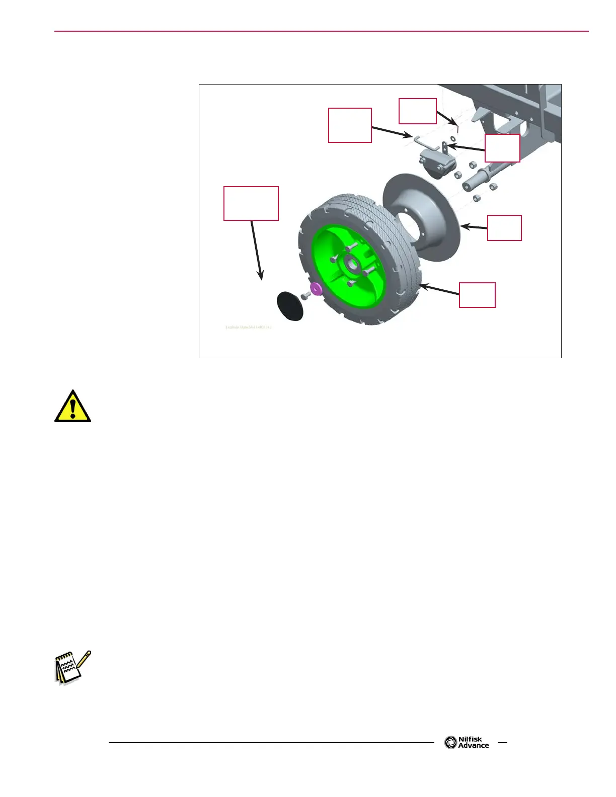
Rear Wheel and Brake Caliper
1. Remove the Cotter Pin
and washer from the
Brake Linkage Rod and
disconnect the Brake
Linkage Rod
from the
top brake arm
mounting hole.
2. Remove the Cotter Pin
and washer from the
Brake Linkage Rod and
disconnect the Brake
Linkage Rod
from the
brake arm mounting hole.
3. Loosen the M10-1.5
x 20mm Hex Screw
holding the Rear Wheel
to the axle.
4. Position a suitable jack
underneath the wheel
axle and jack up the
machine so the wheel is
approximately 1 inch off
the oor.
Warning! Place wood blocking under the rear axle as the machine is only being supported by
the jack. This is to prevent any accidents or machine damage when the wheel is off of
the machine.
5. Remove the M10-1.5 x 20mm Hex Screw and washer and carefully pull the complete wheel and brake
assembly off the axle.
6. If you are replacing the wheel:
a. Remove the four M10-1.5 x 30mm Hex Screws and nuts holding the Brake Rotor to the Rear Wheel hub.
b. Reattach the salvaged Brake Rotor to the new Rear Wheel hub.
7. To reinstall the wheel and brake assembly:
a. Place the brake caliper onto the rotor. Adjust the gap between the pads and the rotor to 0.035”
(0.89mm) using a feeler gauge. See Brake Caliper Pad Wear Adjustment.
b. While holding the caliper on the rotor, and aligning the caliper slots with the chassis, slide the wheel
and brake assembly onto the axle.
c. Install the M10-1.5 x 20mm Hex Screw and washer to fasten the Rear Wheel to the axle.
Service Note: Apply a small amount of Loctite 242 (blue) thread sealant to the M10-1.5 x 20mm Hex
Screw
to prevent the screw from loosening.
d. Remove the wood blocking from the rear axle, then lower the jack.
e. Reconnect the Brake Linkage Rod to the brake arm top hole and reinstall the washer and Cotter Pin.
M10-1.5 x
20mm Hex
Screw
Brake
Arm
Rear
Wheel
Brake
Rotor
Cotter
Pin
Brake
Linkage
Rod

 Loading...