Section 7 System Settings 7-1 Settings
NS-Designer Operation Manual
Reference
♦ Set internal memory for both $SB and $SW allocation addresses or set the same host address for
both for them.
Example $SB: Serial A: 00000
$SW: Serial A: DM 00000
Set the same host name (Serial A) for both $SB and $SW.
♦ TIM, CNT, TK, TU, and CU cannot be allocated for $SB.
♦ TK, TU, and CU cannot be allocated for $SW.
♦ Refer to 2-4 System Memory in the NS Series Programming Manual for details on the system
memory.
♦ When changing the settings on the Comm-All Tab Page for whether the communications port, the
Ethernet, and Controller Link are used, close the System Setting Dialog Box before setting the host
address in $SB or $SW.
R
R
e
e
f
f
e
e
r
r
e
e
n
n
c
c
e
e
$SB, $SW Update Cycle
Data is updated between $SB/$SW and the allocated addresses each time the number of communica-
tions cycles specified in the $SB, $SW Update Cycle field is processed.
Example: When the $SB, $SW Update Cycle is set to three cycles.
123 123
Communications cycle
(time for all required
communications to
complete one cycle.)
Updatin
$SB/$SW
Reference
♦ The $SB and $SW are also updated when a project starts loading, switching base screens, opening
or closing pop-up screens, and switching frames. After updating during these operations, updating
is performed according to the setting in the $SB, $SW Update Cycle field.
R
R
e
e
f
f
e
e
r
r
e
e
n
n
c
c
e
e
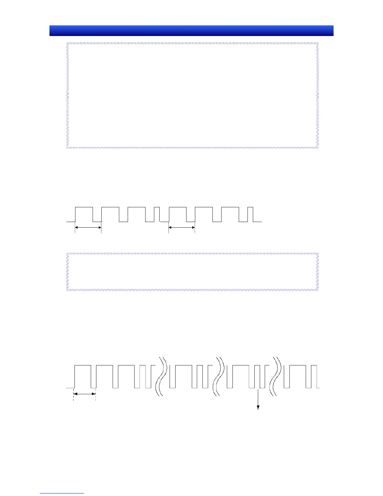
RUN Signal Pulse Interval
The RUN signal ($SB0, $SB1) is output after $SB and $SW are refreshed the number of times set for
the RUN Signal Pulse Interval.
Example: The following illustration is for when the RUN Signal Pulse Interval is set to 3.
Communications cycle (All
required communications
completed once.)
1
$SB and $SW
refreshed
3
$SB and $SW
refreshed
2
$SB and $SW
refreshed
1
$SB and $SW
refreshed
RUN Signal output.
7-3

 Loading...


