4 - 9
4 Part Names and Functions
NX-series EtherCAT Coupler Unit User’s Manual (W519)
4-3 Hardware Switch Settings
4
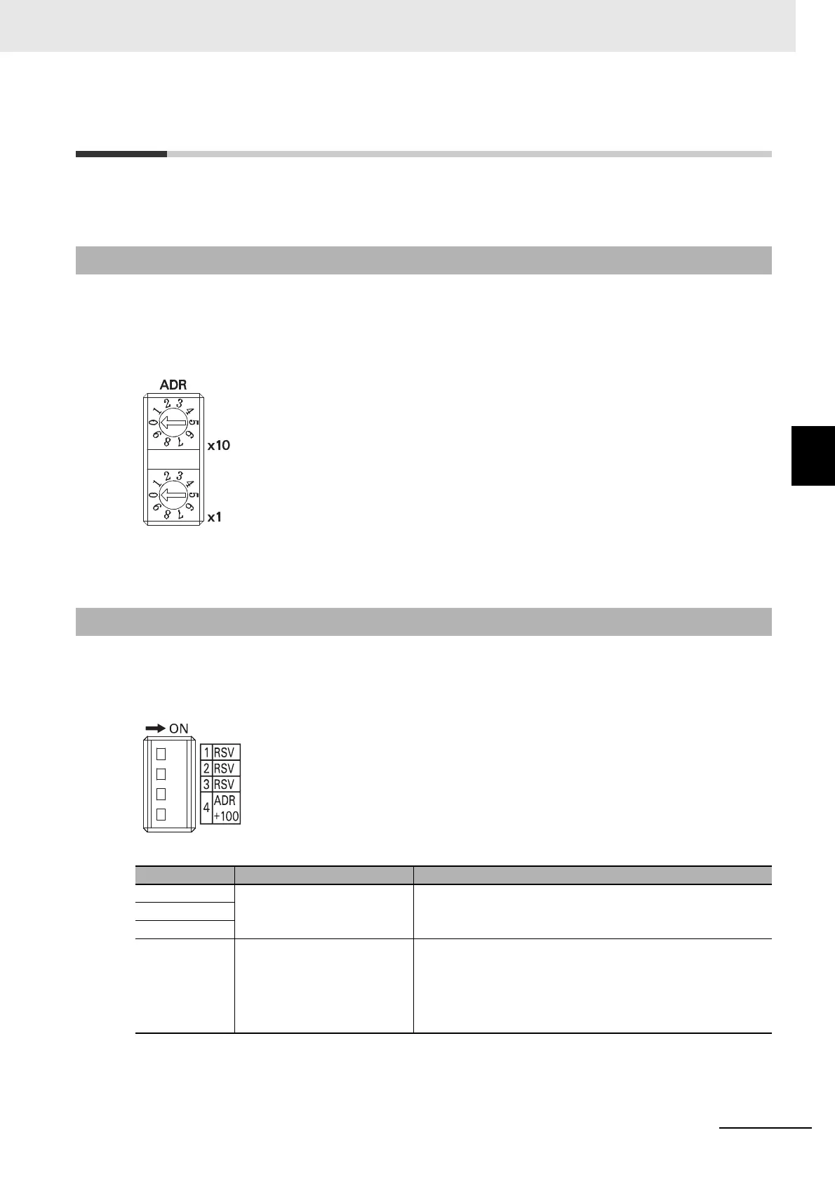
4-3-1 Rotary Switches
4-3 Hardware Switch Settings
This section describes the functions of the hardware switches (i.e., the rotary switches and the DIP
switch) on the front panel of the EtherCAT Coupler Unit.
The rotary switches are used to set the node address of the EtherCAT Slave Terminal on the EtherCAT
network. They set the node address as the 10s digit and 1s digit of the decimal value. The 100s digit is
set on pin 4 of the DIP switch that is described below.
The setting range is from 00 to 99. (The factory setting is 00.)
Refer to 4-3-3 Setting the Node Address on page 4-10 for information on setting the node address by
combining the rotary switches and pin 4 of the DIP switch that is described below.
If you turn ON pin 4 on the DIP switch, 100 will be added to the node address that is set on the rotary
switches.
The other pins are reserved by the system.
Refer to 4-3-3 Setting the Node Address on page 4-10 for information on setting the node address by
combining the rotary switches that are described above and pin 4 of the DIP switch.
4-3-1 Rotary Switches
4-3-2 DIP Switch
Pin Name Meaning
Pin 1 Reserved by the system. Keep turned OFF.
(The factory setting is OFF.)
Pin 2
Pin 3
Pin 4 Node address + 100 ON:
OFF:
The address that is set on the rotary switches is
increased by 100.
The address that is set on the rotary switches is not
increased by 100.
(The factory setting is OFF.)

 Loading...


