4 System Design
4-14
G5 Series AC Servo Drives With Built-in EtherCAT Communications, Linear Motor Type
When wiring the main circuit, use proper wire sizes, grounding systems, and noise resistance.
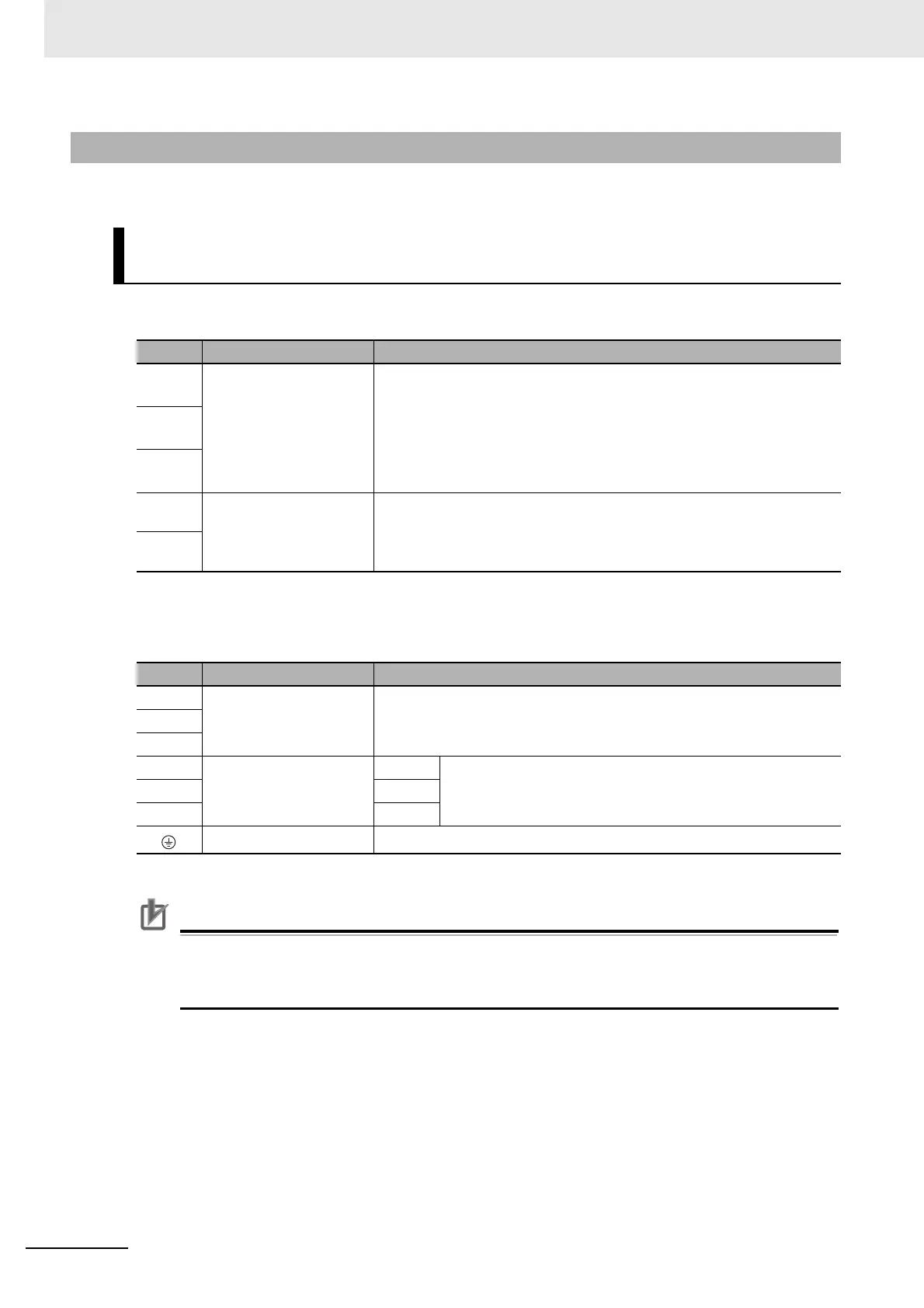
Main Circuit Connector Specifications (CNA)
*1 Single-phase should connect to L1 and L3.
Motor Connector Specifications (CNB)
*1 Do not short B1 and B2. Doing so may result in malfunctioning.
Precautions for Correct UsePrecautions for Correct Use
• Tighten the frame ground screw to a torque of 0.7 to 0.8 N·m (M4).
• If you are connecting an External Regeneration Resistor, set the Regeneration Resistor
Selection servo parameter object (3016 hex).
4-2-2 Main Circuit and Linear Motor Connections
R88D-KN01L-ECT-L/-KN02L-ECT-L/
R88D-KN01H-ECT-L/-KN02H-ECT-L/-KN04H-ECT-L
Symbol Name Function
L1 Main circuit power supply
input
*1
R88D-KNL-ECT-L
100 to 200 W : Single-phase 100 to 120 VAC (85 to 132 VAC) 50/60 Hz
R88D-KNH-ECT-L
100 W to 400 W :
Single-phase or 3-phase 200 to 240 VAC (170 to 264 VAC)
50/60 Hz
L2
L3
L1C Control circuit power
supply input
R88D-KNL-ECT-L :
Single-phase 100 to 120 VAC (85 to 132 VAC) 50/60Hz
R88D-KNH-ECT-L :
Single-phase 200 to 240 VAC (170 to 264 VAC) 50/60 Hz
L2C
Symbol Name Function
B1 External Regeneration
Resistor connection
terminals
*1
Normally B2 and B3 are open. If there is high regenerative energy,
connect an External Regeneration Resistor between B1 and B2.
B3
B2
U Motor connection
terminals
Phase U These are the output terminals to the Linear Motor.
Be sure to wire them correctly.
V Phase V
W
Phase W
Frame ground This is the ground terminal. Ground to 100 or less.

 Loading...

