7-5
7 Applied Functions
G5 Series AC Servo Drives With Built-in EtherCAT Communications, Linear Motor Type
7-1 Sequence I/O Signals
7
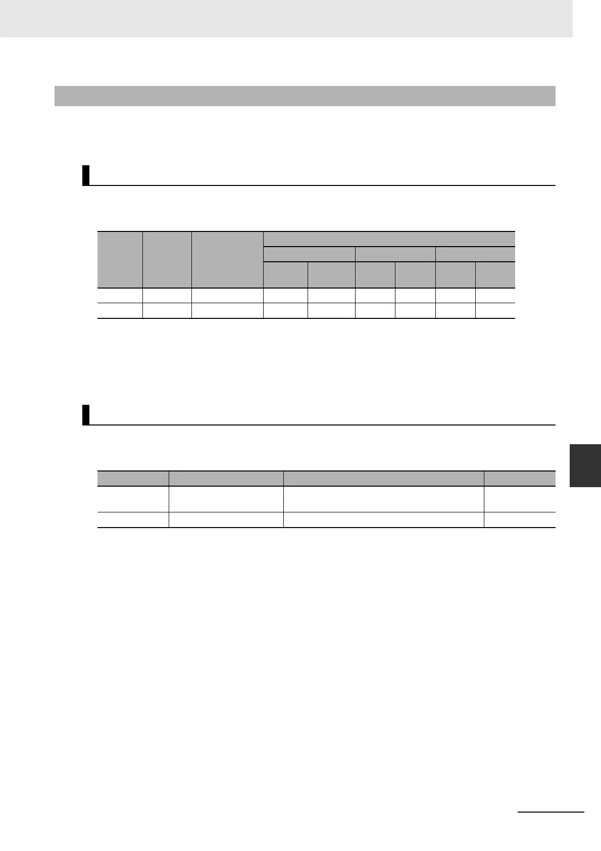
7-1-2 Output Signals
You can allocate output signal functions to the output pins for the control I/O connector (CN1).
In addition, you can change logic.
The allocations of the default output signals are as follows.
Refer to Output Signal Allocation Method on page 7-6 to change the allocations.
Use the following objects when changing the output signal allocations.
For the setting method, refer to Output Signal Allocation Method on page 7-6.
Note For the setting method, refer to Function Number Table on page 7-6.
7-1-2 Output Signals
Output Signal Default Setting
Index
Output
signal
Default setting
(hex)
Default setting state
Position control Speed control Force control
Signal
name
Logic
*1
*1 NO (normally open) and NC (normally close) refer to the following states.
NO: When the function is disabled (OFF state), output transistor is OFF.
When the function is enabled (ON state), output transistor is ON.
NC: When the function is disabled, output transistor is ON.
When the function is enabled, output transistor is OFF.
Signal
name
Logic
*1
Signal
name
Logic
*1
3410 hex OUTM1 0003 0303 hex BKIR NO BKIR NO BKIR NO
3411 hex OUTM2 0002 0202 hex READY NO READY NO READY NO
Objects That Can Be Assigned
Index Object name Explanation Reference
3410 hex Output Signal Selection 1 Set the OUTM1 output function allocation. This
object is set in hexadecimal.
page 9-28
3411 hex Output Signal Selection 2 Set the OUTM2 output function allocation. page 9-28

 Loading...

