11 Adjustment Functions
11-18
G5 Series AC Servo Drives With Built-in EtherCAT Communications, Linear Motor Type
1
Adjust the Position Loop Gain 1 (3100 hex), Speed Loop Gain 1 (3101 hex), Speed Loop
Integral Time Constant 1 (3102 hex), and Force Command Filter Time Constant 1 (3104 hex)
settings.
If no problem occurs in realtime autotuning, you can continue to use the settings.
2
Measure the damping frequency at the tip of the mechanical unit.
Measure the damping frequency by using a measurement device such as a laser displacement
sensor, servo acceleration meter, or acceleration pick-up.
Set the measured damping frequency in one of Damping Frequency 1 to Damping Frequency 4
according to the operation.
Also set the Switching Mode using Damping Filter Selection (3213 hex).
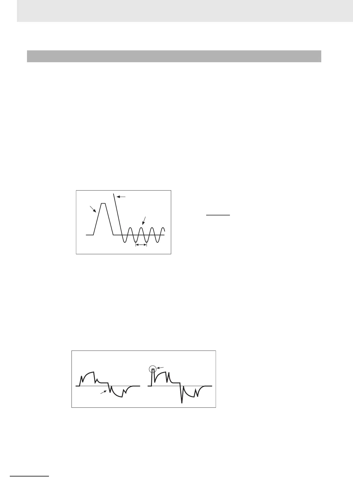
If the measurement device cannot be used, use CX-Drive tracing function, and read the residual
damping frequency [Hz] from the position error waveform as shown in the following figure.
If vibration persists after setting the frequency, increase or decrease the resonance frequency to
find a proper one with minimum vibration.
3
Make the damping filter 1 to 4 settings.
First, set the filter to 0 and check the force waveform during operation.
The stabilization time can be reduced by setting a large value; however, force ripple will increase
at the command change point as shown in the following figure. Set a range that will not cause
force saturation under actual operation conditions. The effects of vibration suppression will be
lost if force saturation occurs.
When setting the damping frequencies, reduce the setting if the force become saturated and
increase the setting to make operation faster. Normally 0 is set.
The setting range is as follows:
11-5-3 Operating Procedure
• The damping frequency in the figure is calculated with
the following formula:
Since the object unit is 0.1 Hz:
(3214 hex, 3216 hex, 3218 hex, 3220 hex) = 10 f
• Application example
If the
damping cycle is 100 ms or 20 ms, set 100 or 500
in the object so that the
damping frequency becomes
10 Hz or 50 Hz.
Command
speed
Position error
Calculate the
damping frequency.
Damping cycle T
Force command
Force saturation
Damping
filter setting is too large.
Damping filter
setting is appropriate.
Damping filter setting range: Damping filter setting
≤
Damping frequency
100
≤
(Damping frequency + Damping filter setting)

 Loading...

