5-60
5
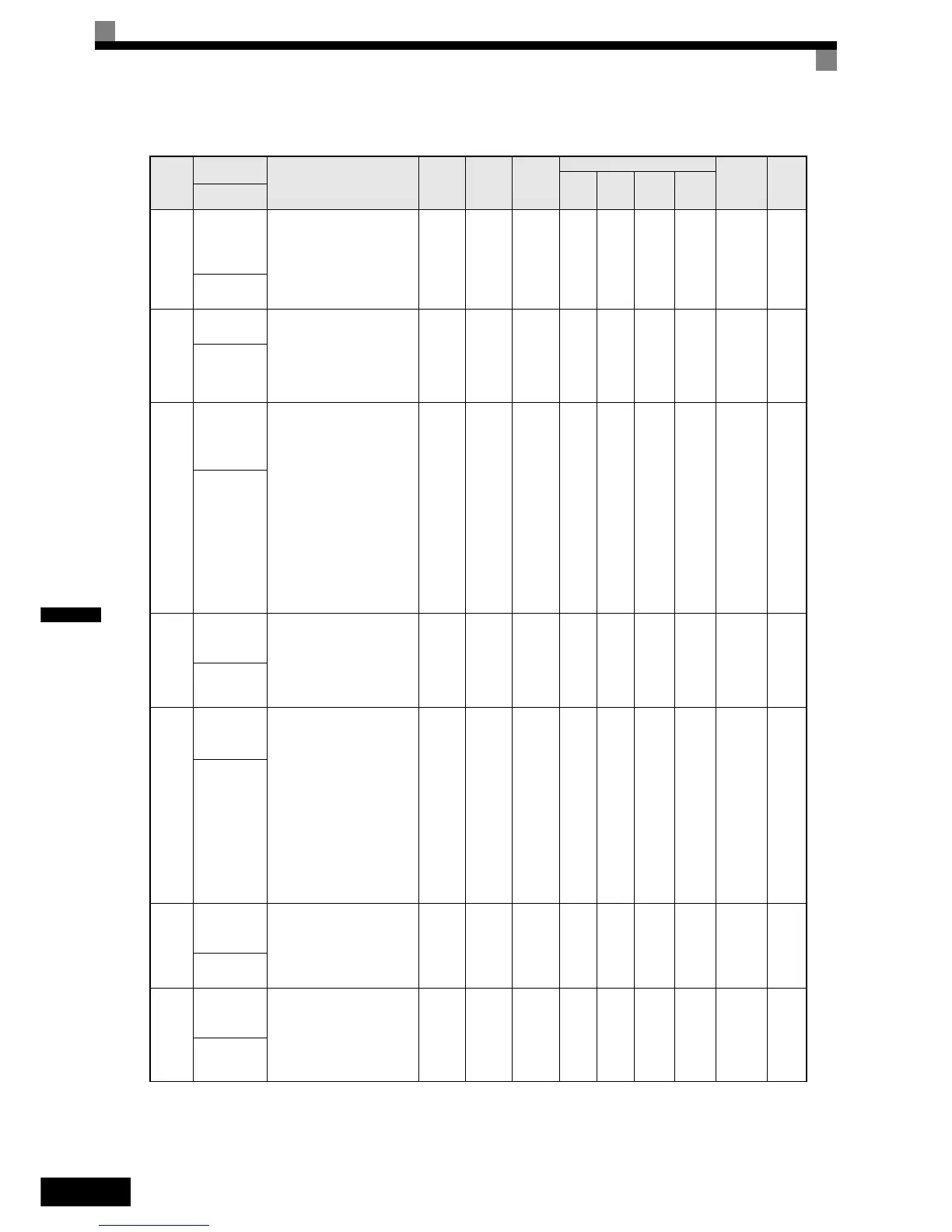
Hardware Protection: L8
Param-
eter
Num-
ber
Name
Description
Setting
Range
Factory
Setting
Change
during
Opera-
tion
Control Methods
MEMO-
BUS
Register
Page
V/f
V/f
with
PG
Open
Loop
Vector
Closed
Loop
Vector
Display
L8-01
Protect selec-
tion for inter-
nal DB
resistor
0: Disabled (no overheating
protection)
1: Enabled (overheating
protection)
0 or 1 0 No A A A A 4ADH 6-63
DB Resistor
Prot
L8-02
Overheat pre-
alarm level
Sets the detection temperature
for the Inverter overheat
detection pre-alarm in °C.
The pre-alarm detects when
the cooling fin temperature
reaches the set value.
50 to
130
95 °C* No A A A A 4AEH 6-64
OH Pre-
Alarm Lvl
L8-03
Operation
selection
after overheat
pre-alarm
Sets the operation for when
the Inverter overheat pre-
alarm occurs.
0: Decelerate to stop using
the deceleration time C1-
02.
1: Coast to stop
2: Fast stop in fast-stop time
C1-09.
3: Continue operation
(Monitor display only.)
A fault will be given in setting
0 to 2 and a alarm will be
given in setting 3.
0 to 3 3 No A A A A 4AFH 6-64
OH Pre-
Alarm Sel
L8-05
Input open-
phase protec-
tion selection
0: Disabled
1: Enabled (Detects power
supply open-phase, power
supply voltage imbalance
or DC bus electrostatic
capacitor deterioration.)
0 or 1 1 No A A A A 4B1H 6-64
Ph Loss In
Sel
L8-07
Output open-
phase protec-
tion selection
0: Disabled
1: Enabled, 1 Phase Observa-
tion
2: Enabled, 2 and 3 Phase
Observation
An output open-phase is
detected at less than 5% of
Inverter rated current.
When the applied motor
capacity is small compared to
the Inverter capacity, the
detection may not work prop-
erly and should be disabled.
0 or 2 0 No A A A A 4B3H 6-65
Ph Loss Out
Sel
L8-09
Ground pro-
tection selec-
tion
0:Disabled
1:Enabled
It is not recommended to use
another setting than factory
setting.
0 or 1 1 No A A A A 4B5H 6-65
Ground Fault
Sel
L8-10
Cooling fan
control selec-
tion
Set the ON/OFF control for
the cooling fan.
0: ON when Inverter is
running only
1: ON whenever power is
ON
0 or 1 0 No A A A A 4B6H 6-65
Fan On/Off
Sel
 Loading...


