6-146
6
Option Cards
Using PG Feedback Option Cards
To get a more precise speed control the inverter can be equipped with a PG option card to connect a pulse gen-
erator. Three different PG cards can be used, the PG-B2, the PG-X2 and the PG-Z2. Refer to page 2-30,
Option Card Models and Specifications to see details.
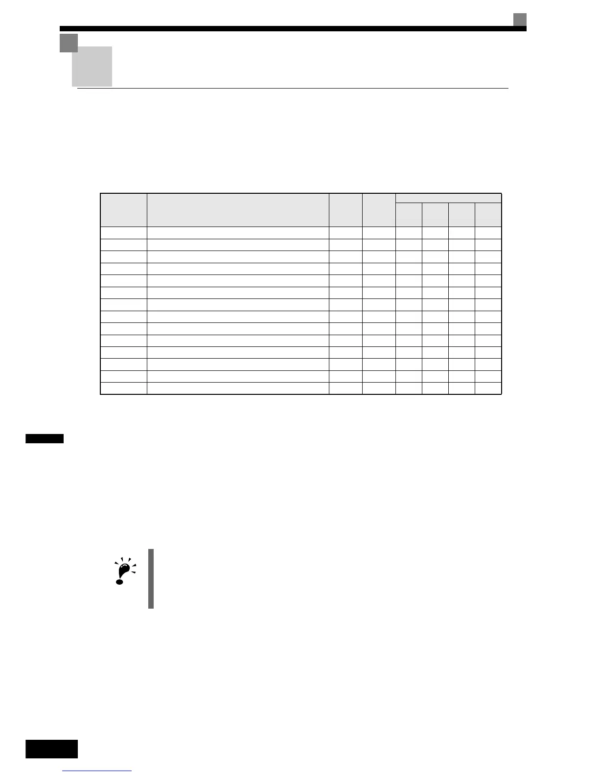
Related Parameters
Using PG Speed Control Card
There are two types of PG Speed Control Card that can be used in V/f control with PG and Closed Loop Vec-
tor control:
• PG-B2: A/B-phase pulse input, compatible with complementary outputs.
• PG-X2: A/B/Z-phase pulse input, compatible with line drivers (RS-422).
• PG-Z2: Dual encoder PG feedback card (two times phase A, B, Z), selectable line driver (RS422) or open collector
inputs
For the mounting instructions, specifications and connection diagrams refer to page 2-30, Installing and Wir-
ing Option Cards.
Setting Number of PG Pulses (F1-01)
Set the number of PG (Pulse Generator/Encoder) pulses in pulses per revolution.
Parameter
No.
Name
Factory
Setting
Change
during
Opera-
tion
Control Methods
V/f
V/f with
PG
Open
Loop
Vector
Closed
Loop
Vector
F1-01 PG constant 1024 No No Q Q Q
F1-02 Operation selection at PG open circuit (PGO) 1 No No A No A
F1-03 Operation selection at overspeed (OS) 1 No No A No A
F1-04 Operation selection at deviation (DEV) 3 No No A No A
F1-05 PG rotation 0 No No A A A
F1-06 PG division rate (PG pulse monitor) 1 No No A A A
F1-07 Integral value during accel/decel enable/disable 0 No No A No A
F1-08 Overspeed (OS) detection level 115% No No A No A
F1-09 Overspeed detection delay time (OS) 1.0 s No No A No A
F1-10 Excessive speed deviation (DEV) detection level 10% No No A No A
F1-11 Excessive speed deviation detection delay time (DEV) 0.5 s No No A No A
F1-12 Number of PG gear teeth 1 0 No No A No A
F1-13 Number of PG gear teeth 2 0 No No A No A
F1-14 PG open-circuit detection delay time 2.0 s No No A No A
IMPORTANT
If Open Loop Vector control is used and a PG card is installed, the speed detected by the PG card is dis-
played in the monitor parameter U1-05. Therefore the PG constant has to be set in parameter F1-01. The
direction of the speed detection can be changed by parameter F1-05.
To change the U1-05 value to the internally calculated value remove the PG card.
 Loading...


