6-48
6
Setting Precautions
• When the output torque reaches the torque limit, control and compensation of the motor speed is disabled
to prevent the output torque from exceeding the torque limit. The torque limit has the priority.
• When using the torque limit for hoist applications, do not carelessly lower the torque limit value, as this
may result in motor stalling.
• When using an analog input for torque limit setting, an analog input value of 10 V/20 mA is equal to a
torque limit of 100% of the motor rated torque. To raise the torque limit value at an analog input of 10 V/
20 mA for instance to 150% of the rated torque, set the input terminal gain to 150.0 (%). Adjust the gain
for multi-function analog input terminal A2 using H3-10.
• The torque limit accuracy is ±5% at an output frequency of 10 Hz or above. When output frequency is
lower than 10 Hz, the accuracy is lowered.
Preventing Motor Stalling During Operation
Stall prevention during run prevents the motor from stalling by automatically lowering the inverter output fre-
quency when a transient overload occurs while the motor is operating at a constant speed.
Stall prevention during operation can be enabled in V/f control with/without PG only. If the Inverter output
current continues to exceed the setting in parameter L3-06 for 100 ms or longer, the motor speed is reduced.
Enable or disable the stall prevention using parameter L3-05. Set the according deceleration times using C1-
02 (Deceleration time 1) or C1-04 (Deceleration Time 2).
If the Inverter output current reaches the set value in L3-06 – 2%, the motor will accelerate again to the set fre-
quency.
Related Parameters
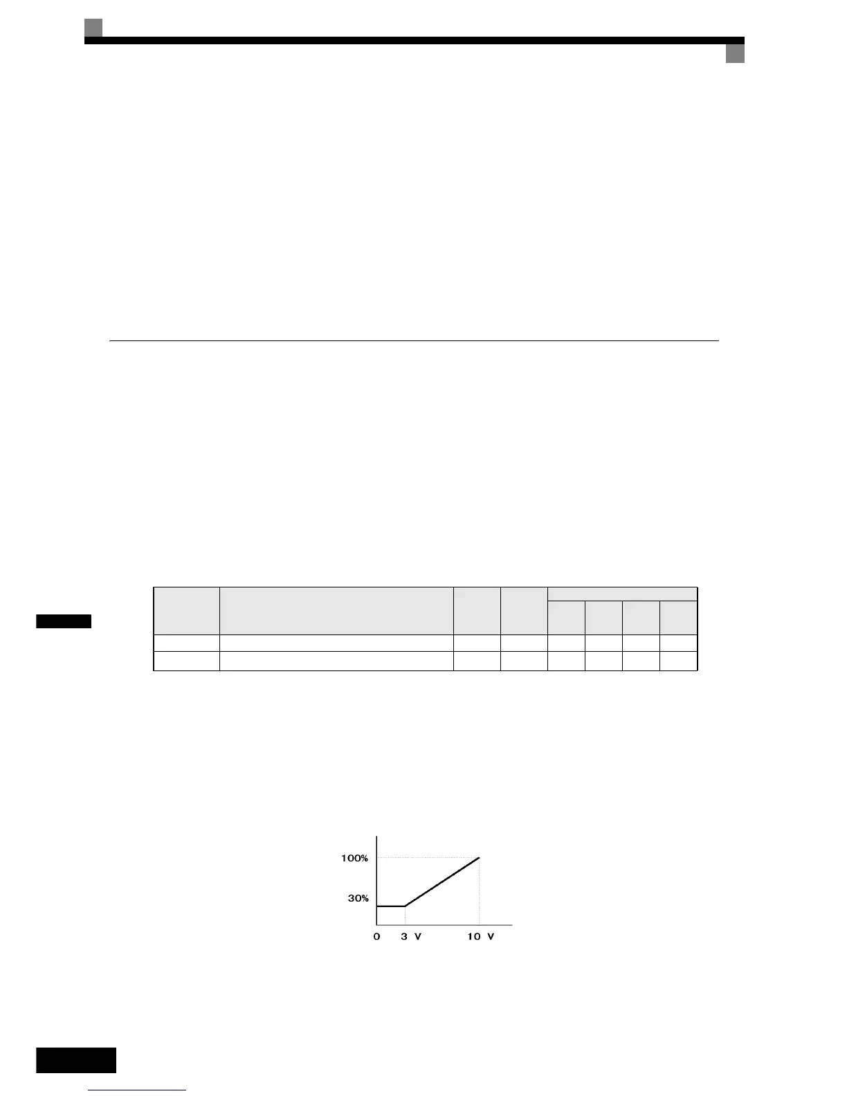
Changing Stall Prevention Level during Operation Using an Analog Input
If H3-09 (Analog Input Terminal A2 Function Selection) is set to 8 (stall prevention level during run), the stall
level during operation can be changed using the analog input A2.
In this case the function uses either the value from the multi-function analog input terminal A2 input level or
the set value in parameter L3-06. The lower value of both will be used as stall prevention level.
Fig 6.51 Stall Prevention Level during Operation Using an Analog Input
If the motor capacity is smaller than the Inverter capacity or the motor stalls when operating at the factory set-
tings, lower the stall prevention level during operation.
Parameter
No.
Name
Factory
Setting
Change
during
Opera-
tion
Control Methods
V/f
V/f with
PG
Open
Loop
Vector
Closed
Loop
Vector
L3-05 Stall prevention selection during run function selection 1 No A A No No
L3-06 Stall prevention level during run
150%
* 1
* 1. Shows the initial value when C6-01 is set to 0 (default). If C6-01 is set to 1 or 2, the initial value is 120%
No A A No No
Stall prevention level during run
Multi-function analog input
terminal A2 input level
 Loading...


