2-18
2
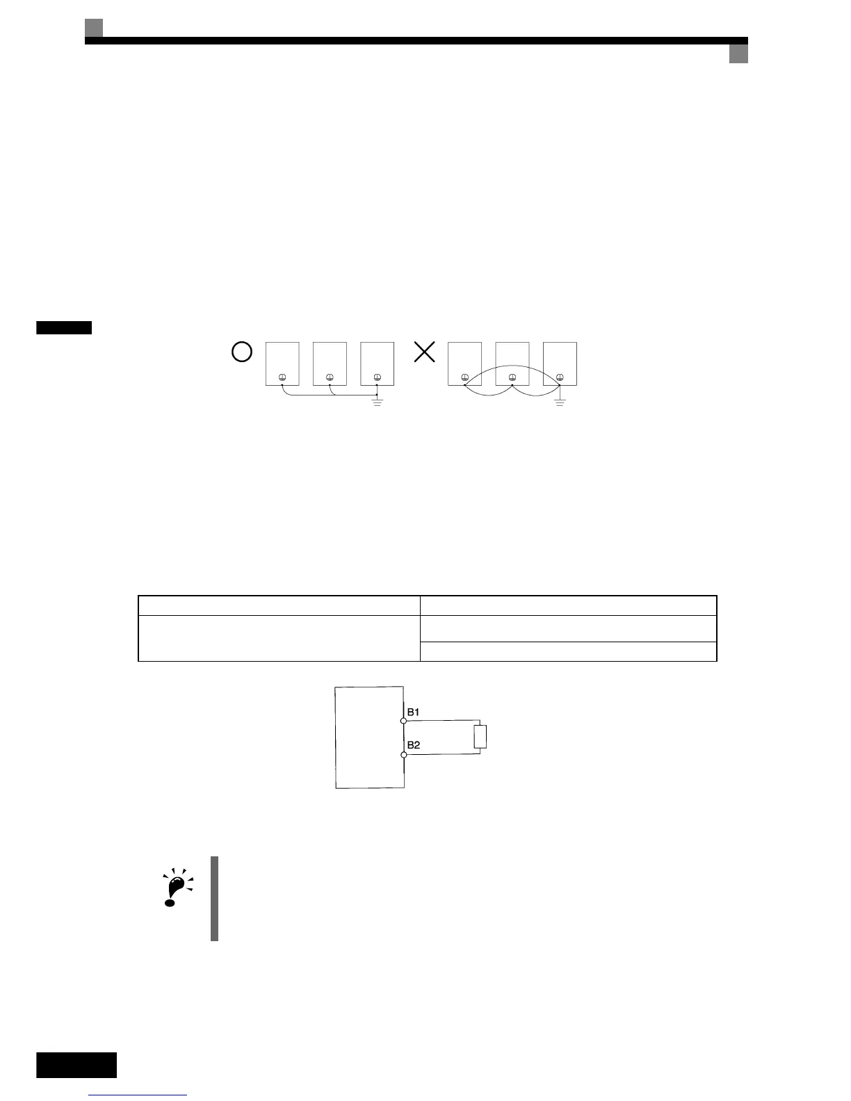
Ground Wiring
Observe the following precautions when wiring the ground line.
• Always use the ground terminal of the 200 V Inverter with a ground resistance of less than 100 Ω and that
of the 400 V Inverter with a ground resistance of less than 10 Ω.
• Do not share the ground wire with other devices, such as welding machines or power tools.
• Always use a ground wire that complies with technical standards on electrical equipment and minimize the
length of the ground wire.
Leakage current flows through the Inverter. Therefore, if the distance between the ground electrode and the
ground terminal is too long, potential on the ground terminal of the Inverter will become unstable.
• When using more than one Inverter, be careful not to loop the ground wire.
Fig 2.6 Ground Wiring
Connecting a Inverter Back Mounted Braking Resistor
A Braking Resistor mounted to back side of the Inverter can be used with 200 V and 400 V Class Inverters
with outputs from 0.4 to 11 kW. If this type of resistor is used, the internal braking resistor overheat protection
can be enabled (see Table below).
Connect the braking resistor as shown in Fig 2.7.
Fig 2.7 Connecting the Braking Resistor
L8-01 (Protection selection for internal DB resistor) 1 (Enable overheat protection)
L3-04 (Stall prevention selection during deceleration)
(Select either of them.)
0 (Disable stall prevention function)
3 (Enable stall prevention function with braking resistor)
IMPORTANT
The braking resistor connection terminals are B1 and B2. Do not connect the resistor to any other termi-
nals. Otherwise the resistor and other equipment may get damaged
OK
NO
Inverter
Braking resistor
 Loading...


