2-27
2
Safe Disable Input Precautions
The Safe Disable Function (Hardware Baseblock inputs) is only available in the Inverter Version with Safety
(Inverter with spec C).
Safe Disable Function Description
The Safe Disable function can be utilized to perform a safe stop according to the EN60204-1, Stop Category 0
(uncontrolled stop by power removal). It is designed to meet the requirements of the EN954-1, Safety Cate-
gory 3.
Removing the voltage from both terminals BB and BB1 disables the drive output, i.e. the power supply to the
motor is cut by stopping the switching of the output transistors in a safe way. “BB” is shown on the display.
Installation
1. If the Safe Disable function is utilized, the wire link between the terminals SN, BB, and BB1 that is pre-
installed at the shipment has to be removed entirely
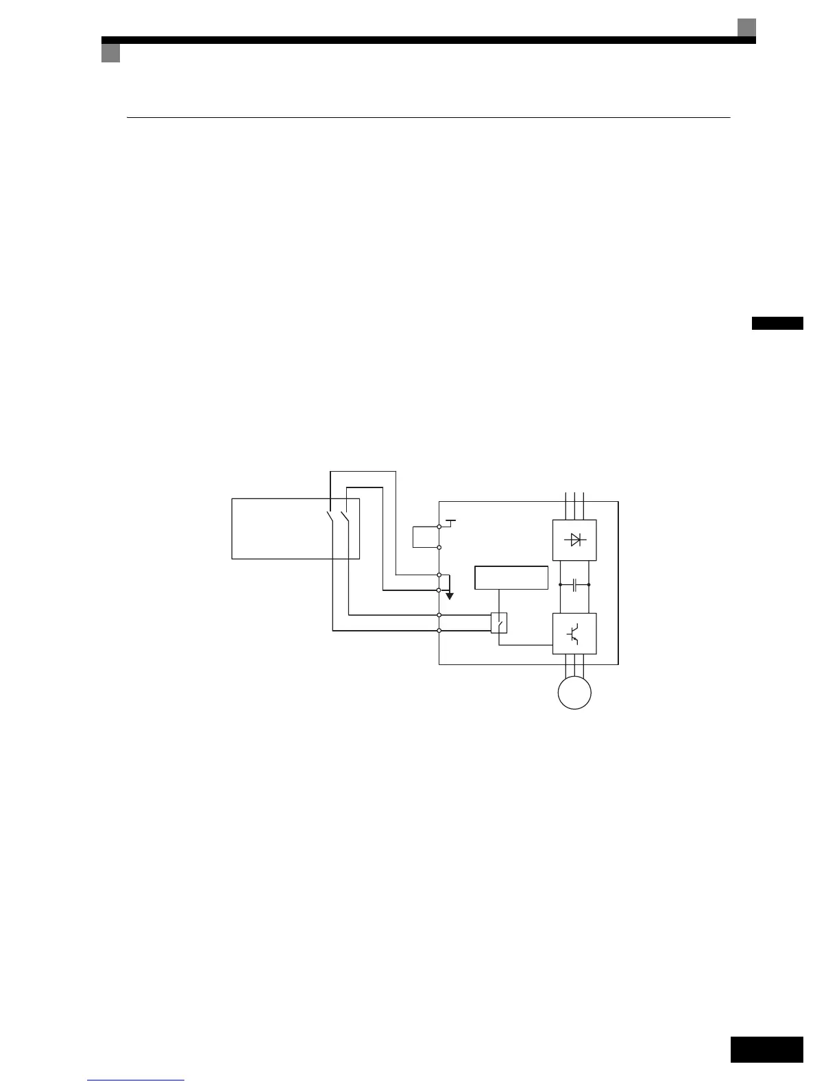
2. Connect the drive to an EN954-1, Safety Category 3 interrupting device so that in case of a Safe Disable
request the connection between the terminal SN and both terminals BB and BB2 are opened.
Fig 2.15 Wiring the Hardware Baseblock
Notes:
1. To assure that the Safe Disable function appropriately fulfills the safety requirements of the application, a
throughout risk assessment shall be done according to ISO12100 for the whole safety systems at the final
installation.
2. If only one signal line from the safety device to the drive is used (“BB” and “BB1” are linked at the drive),
the drive must be installed in an enclosure with protection degree of at least IP54 in order to maintain
EN954-1, safety category 3 compliance. If two separate signal lines from the safety device to the inputs
“BB” and “BB1” are used (like shown above), the drive must not necessarily be installed in an IP54 enclo-
sure.
3. If the safety device and the drive are installed in separate cabinets, the Safe Disable wire must be installed
in a short circuit proof way.
4. The Safe Disable function does not cut the power supply to the drive and does not provide electrical isola-
tion. Before any installation or maintenance work is done, the drive’s power supply must be switched off.
5. The time from opening the Safe Disable input until the drive output is swithced off is less than 10 msec.
SN
BB1
M
BB
SN
SC
SP
24V
EN954-1
Safety Cat. 3
Device
Drive
Power Supply
Controller
 Loading...


