6-51
6
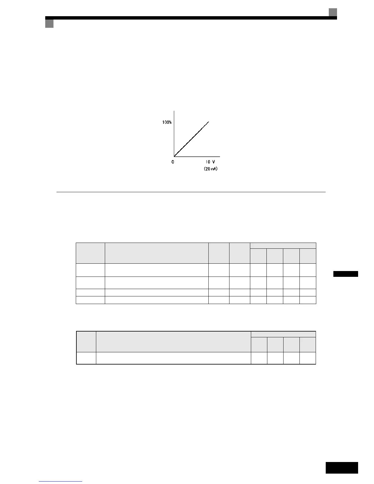
Changing Overtorque and Undertorque Detection Levels Using an Analog Input
If parameter H3-09 (Analog Input Terminal A2 Function Selection) is set to 7 (overtorque/undertorque detec-
tion level), the overtorque/undertorque detection level can be changed using the analog input A2 (refer to Fig
6.54).
Only the overtorque/undertorque detection level 1 can be changed using the analog input. Overtorque/under-
torque detection level 2 cannot be changed by an analog input signal.
Fig 6.54 Overtorque/Undertorque Detection Level Using an Analog Input
Motor Overload Protection
The motor can be protected from overload using the built-in electronic thermal overload relay function.
Related Parameters
Multi-Function Outputs (H2-01 to H2-03)
Setting Motor Rated Current (E2-01 and E4-01)
Set the rated current value on the motor nameplate in parameters E2-01 (for motor 1) and E4-01 (for motor 2).
This set value is the base current for the internal thermal overload calculation.
Parameter
No.
Name
Factory
Setting
Change
during
Opera-
tion
Control Methods
V/f
V/f with
PG
Open
Loop
Vector
Closed
Loop
Vector
E2-01 Motor rated current
1.90 A
* 1
* 1. The factory setting depends on the Inverter capacity (the value shown is for a 200 V Class inverter with 0.4kW)
No QQQQ
E4-01 Motor 2 rated current
1.90 A
*1
No AAAA
L1-01Motor protection selection 1 No QQQQ
L1-02 Motor protection time constant 1.0 min No AAAA
Set
Value
Function
Control Methods
V/f
V/f
with
PG
Open
Loop
Vector
Closed
Loop
Vector
1F
During motor overload (OL1, including OH3) pre-alarm (ON: 90% or more of the detection
level)
Yes Yes Ye s Ye s
(4 mA)
Detection level
Multi-function analog input
terminal A2 input level
 Loading...


