6-120
6
Setting the V/f Pattern 2
Using the E3- parameters the V/f pattern for motor 2 can be set as needed.
It is not recommended to change the settings when the motor is used in open loop vector mode.
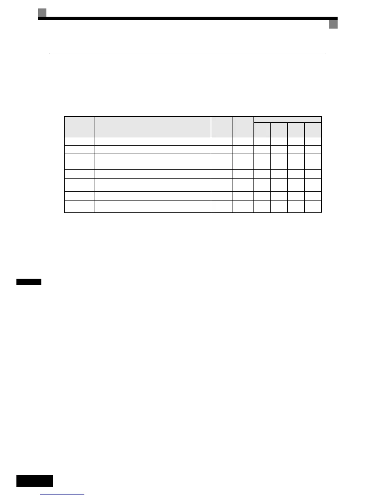
Related Parameters
Selecting the Motor 2 Control Method (E3-01)
Using parameter E3-01 the control method for motor 2 can be selected.
• The setting of this parameter affects the autotuning function. If V/f or V/f with PG is selected the only pos-
sible autotuning method will be stationary autotuning for line-to-line resistance.
Setting the V/f Pattern Characteristic
The principle of setting the V/f pattern 2 is the same as for V/f pattern 1.
Please refer to page 6-114, Setting V/f Pattern (E1-02) for details.
Note: The V/f pattern 2 settings are only used for motor 2, i.e. motor 2 has to be selected using a multi-
function digital input (H1- = 16).
Parameter
No.
Name
Factory
Setting
Change
during
Opera-
tion
Control Methods
V/f
V/f with
PG
Open
Loop
Vector
Closed
Loop
Vector
E3-01 Motor 2 control method selection 0 No A A A A
E3-02 Motor 2 max. output frequency (FMAX) 50.0 Hz No A A A A
E3-03 Motor 2 max. output voltage (VMAX)
200.0 V
* 1
* 1. These are values for a 200 Vclass Inverter. Values for a 400 V class Inverter are double.
No AAAA
E3-04 Motor 2 max. voltage frequency (FA) 50.0 Hz No A A A A
E3-05 Motor 2 mid. output frequency 1 (FB)
2.5 Hz
* 2
* 2. The factory setting will change when the control method is changed. (V/f control factory settings are given.)
No A A A No
E3-06 Motor 2 mid. output frequency voltage 1 (VB)
15.0 V
*1
*2
No A A A No
E3-07 Motor 2 min. output frequency (FMIN)
1.2 Hz
*2
No AAAA
E3-08 Motor 2 min. output frequency voltage (VMIN)
9.0 V
*1 *2
No A A A No
 Loading...


