6-85
6
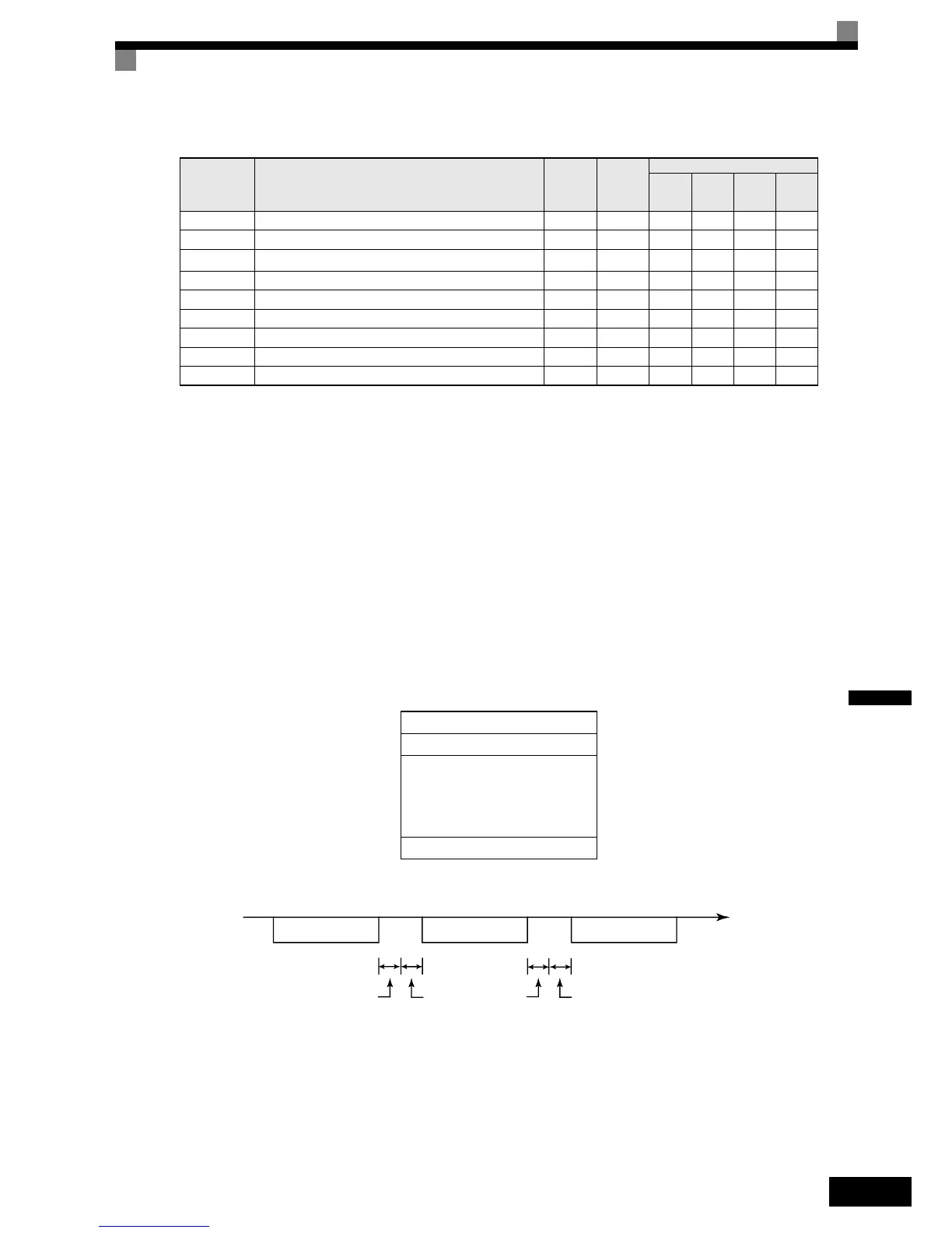
Related Parameters
MEMOBUS communications can perform the following operations regardless of the settings in b1-01 and
b1-02.
• Monitoring operation status of the inverter
• Setting and reading parameters
• Resetting faults
• Inputting multi-function commands. (An OR operation is performed between the multi-function com-
mands input from the PLC and commands input from digital input terminals S3 to S7.)
Message Format
In MEMOBUS communications, the master sends commands to the slave, and the slave responds. The mes-
sage format is configured for both sending and receiving as shown below, and the length of data packets
depends on the command (function) content.
The space between messages must meet the following conditions:
Fig 6.77 Message Spacing
Slave Address
Set the Inverter address from 0 to 31. If you set 0, commands from the master will be received by all slaves.
(Refer to “Broadcast Data” on the following pages.)
Parameter
No.
Name
Factory
Setting
Change
during
Opera-
tion
Control Methods
V/f
V/f with
PG
Open
Loop
Vector
Closed
Loop
Vector
b1-01Reference source selection 1 No QQQQ
b1-02RUN command Source Selection 1 No QQQQ
H5-01 Station address
1F
* 1
* 1. Set H5-01 to 0 disable Inverter responses to MEMOBUS communications.
No AAAA
H5-02Baud rate selection 3 No AAAA
H5-03Communications parity selection 0 No AAAA
H5-04Communications fault detection selection 3 No AAAA
H5-05Communications fault detection selection 1 No AAAA
H5-06Send wait time 5 ms No AAAA
H5-07RTS control ON/OFF 1 No AAAA
Slave address
Function code
Data
Error check
PLC to Inverter
Inverter to PLC
PLC to Inverter
Command message
Response message
Command message
Time (Seconds)
24 bits long
5 ms min.
H5-06
setting
24 bits long
 Loading...


