6-54
6
Terminal Connection
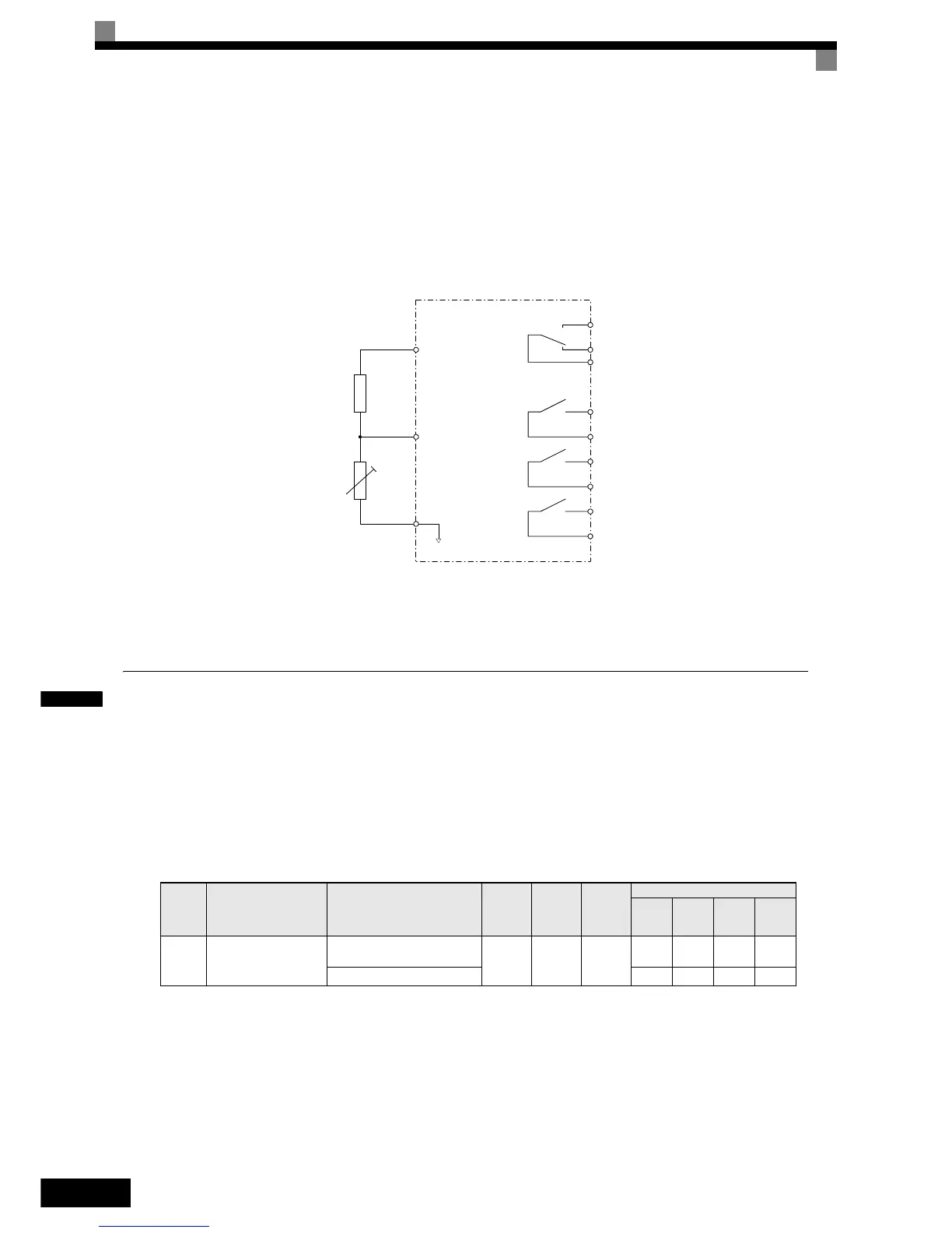
The terminal connection for the motor overheat function is shown in Fig 6.57. The following points have to be
considered:
• Pin 2 of the DIP-switch S1 on the control terminal board has to be turned to OFF for voltage input at termi-
nal A2. The factory setting is ON (current input).
• Parameter H3-09 has to be set to “E”
• Parameter H3-08 (analog input terminal A2 signal level) has to be set to 0 (0-10V input).
Fig 6.57 Terminal Connections for Motor Overheating Protection
Limiting Motor Rotation Direction and Output Phase Rotation
If the motor reverse rotation is prohibited, a reverse run command will not be accepted, even if it is input. Use
this setting for applications in which reverse motor rotation can cause problems (e.g., fans, pumps, etc.)
In V/f and Open Loop Vector control mode it is also possible to change the output phase order by changing a
parameter. This is much easier and faster than changing the wiring if the motor rotational direction is wrong. If
this function is used a prohibition of reverse direction is not possible.
Related Parameters
Param-
eter
Number
Name Description
Setting
Range
Factory
Setting
Change
during
Opera-
tion
Control Methods
V/f
V/f
with
PG
Open
Loop
Vector
Closed
Loop
Vector
b1-04
Prohibition of reverse
operation
0: Reverse enabled
1: Reverse disabled
0 or 2
* 1
* 1. The setting range is 0 and 1 for Closed Loop Vector control and V/f control with PG.
0No
AAAA
2: Output Phase Rotation A No A No
+V (15V, 20mA)
A2 , 0-10V
AC
Branch resistance
18kOhm*
PTC thermistor
MA
MB
MC
M1
M2
M3
M4
M5
M6
*1
The resistance value of 18 kΩ is only valid when a 3-phase PTC with the characteristic shown on the pre-
vious page is used.
 Loading...


