2-34
2
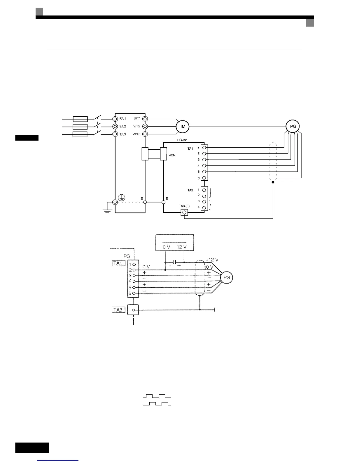
Wiring
Wiring the PG-B2
The following illustrations show wiring examples for the PG-B2 using the option cards power supply or an
external power source for supplying the PG.
Fig 2.17 PG-B2 Wiring Using the Option Cards Power Supply
Fig 2.18 PG-B2 Wiring Using a 12 V External Power Supply
• Shielded twisted-pair wires must be used for signal lines.
• Do not use the pulse generator's power supply for anything other than the pulse generator (encoder). Using
it for another purpose can cause malfunctions due to noise.
• The length of the pulse generator's wiring must not be more than 100 meters.
• The direction of rotation of the PG can be set in user parameter F1-05. The factory preset if for forward
rotation, A-phase advancement.
• When connecting to a voltage-output-type PG (encoder), select a PG that has an output impedance with a
current of at least 12 mA to the input circuit photocoupler (diode).
• The pulse monitor dividing ratio can be changed using parameter F1-06.
Three-phase
Inverter
Power supply +12 V
Power supply 0
Pulse input phase A
GND pulse input phase A
Pulse input phase B
GND pulse input phase B
Pulse monitor output phase A
Pulse monitor output phase B
CN4CN4
R/L1
S/L2
T/L3
A-phase pulses
B-phase pulses
 Loading...


