6-31
6
Related Parameters
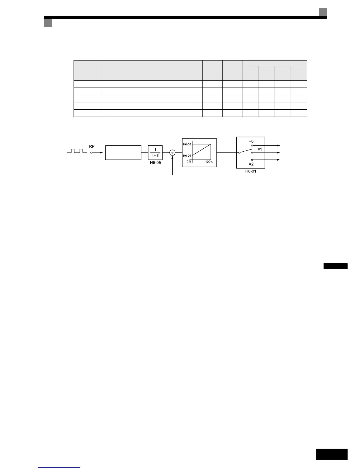
The block diagram in Fig 6.37 explains the functioning of the pulse train input.
Fig 6.37 Frequency Reference Adjustments Using Pulse Train Inputs
The principle for setting the input gain and bias is the same as for the analog inputs (refer to page 6-27). The
only difference is that the input signal is not a voltage or a current but a pulse train.
Parameter
No.
Name
Factory
Setting
Change
during
Opera-
tion
Control Methods
V/f
V/f with
PG
Open
Loop
Vector
Closed
Loop
Vector
H6-01Pulse train input function selection 0 No AAAA
H6-02 Pulse train input scaling 1440 Hz Yes AAAA
H6-03Pulse train input gain 100.0%Yes AAAA
H6-04Pulse train input bias 0.0%Yes AAAA
H6-05 Pulse train input filter time 0.10 s Yes AAAA
Cycle
measurement
Filter
Gain and bias
Scaling using H6-02
Master speed frequenc
 Loading...


