6-73
6
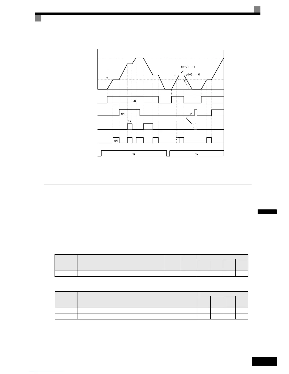
Fig 6.70 UP/DOWN Commands Timing Chart
Adding/Subtracting a Fixed Speed to an Analog Reference (Trim Control)
The trim control function adds or subtracts the value of parameter d4-02 to/from an analog frequency refer-
ence.
To use this function, set two of the parameters H1-01 to H1-05 (multi-function digital terminal inputs S3 to S7
function selection) to 1C (Trim Control Increase command) and 1D (Trim Control Decrease command). Be
sure to allocate two terminals so that the Trim Control Increase command and Trim Control Decrease com-
mand are used as a pair. Otherwise an OPE03 alarm will be displayed.
Related Parameters
Multi-function Digital Inputs (H1-01 to H1-05)
Parameter
No.
Name
Factory
Setting
Change
during
Opera-
tion
Control Methods
V/f
V/f with
PG
Open
Loop
Vector
Closed
Loop
Vector
d4-02Trim control speed limits 10% No AAAA
Set Value Function
Control Methods
V/f
V/f
with
PG
Open
Loop
Vector
Closed
Loop
Vector
1C Trim control increase Yes Yes Yes Yes
1D Trim control decrease Yes Yes Yes Yes
Output frequency
Upper limit (d2-01)
Accelerates to
lower limit
Same
frequency
Lower limit (d2-02)
Forward operation/stop
UP command
DOWN command
Speed agree*
Reference
frequency reset
Power supply
* The speed agree signal turns ON when the motor is not accelerating/decelerating while
the run command is ON.
 Loading...


