6-80
6
Monitor Parameters
Using the Analog Monitor Outputs
This section explains the usage of the internal analog monitor outputs.
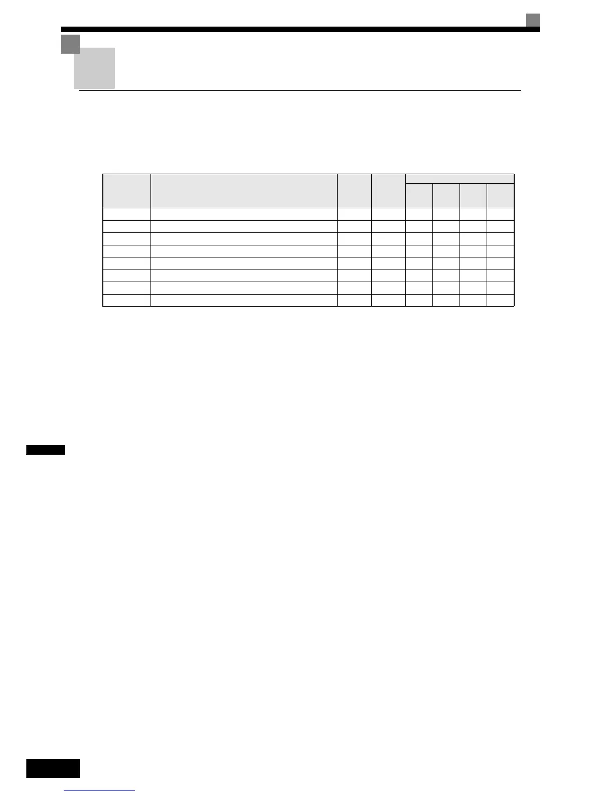
Related Parameters
Selecting Analog Monitor Items
Some of the digital operator monitor items (U1- [status monitor]) can be output at the multi-function ana-
log output terminals FM-AC and AM-AC. Refer to page 5-70, Status Monitor Parameters: U1 and set the
parameter number of U1 group (
part of U1-) for the parameters H4-01 or H4-04.
Adjusting the Analog Monitor Items
Adjust the output current/voltage for multi-function analog output terminals FM-AC and AM-AC using the
gain and bias in H4-02, H4-03, H4-05, and H4-06.
The gain sets the analog output voltage/current value which is equal to 100% of the monitor item.
The bias sets the analog output voltage/current value which is equal to 0% of the monitor item.
Note that the maximum output voltage/current is 10V/20mA. A voltage/current higher than these values can
not be output.
Parameter
No.
Name
Factory
Setting
Change
during
Opera-
tion
Control Methods
V/f
V/f with
PG
Open
Loop
Vector
Closed
Loop
Vector
H4-01 Monitor selection (terminal FM) 2 No A A A A
H4-02 Gain (terminal FM) 100% Yes Q Q Q Q
H4-03 Bias (terminal FM) 0.0% Yes A A A A
H4-04 Monitor selection (terminal AM) 3 No A A A A
H4-05 Gain (terminal AM) 50% Yes Q Q Q Q
H4-06 Bias (terminal AM) 0.0% Yes A A A A
H4-07 Analog output 1 signal level selection (FM) 0 No A A A A
H4-08 Analog output 2 signal level selection (AM) 0 No A A A A
 Loading...


