6-71
6
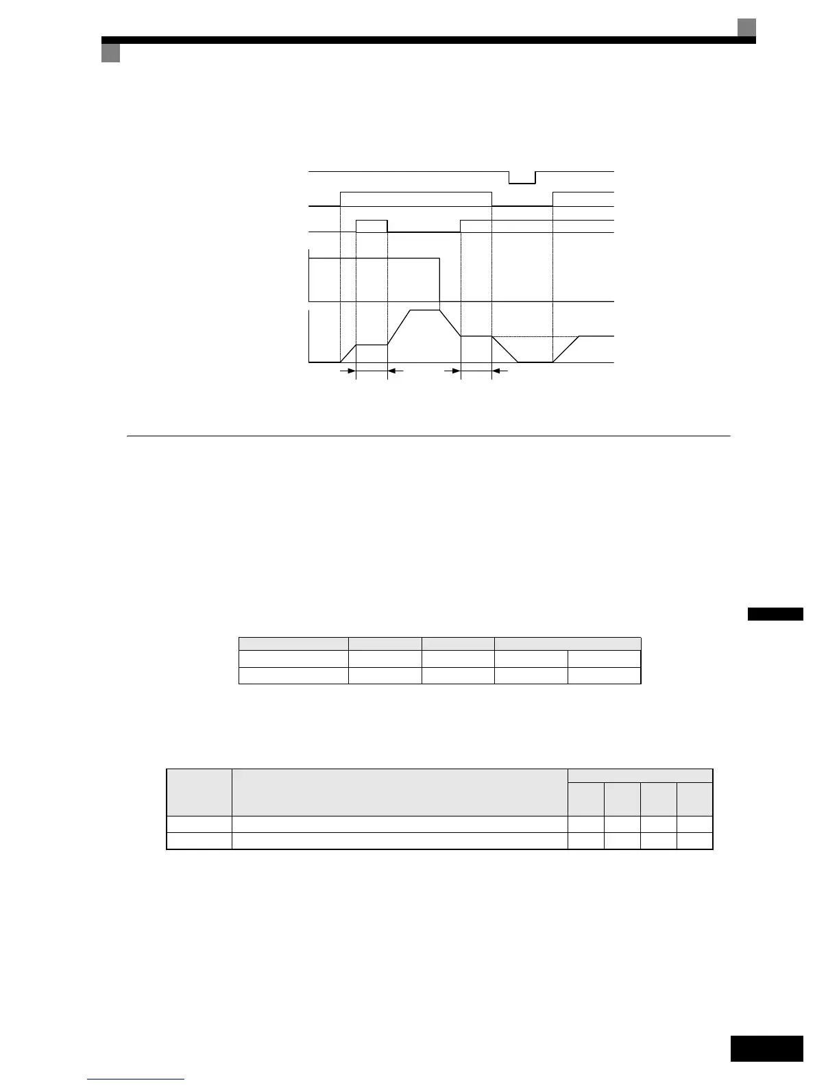
Timing Chart
The timing chart when using Acceleration/Deceleration Ramp Hold commands is shown in Fig 6.68.
Fig 6.68 Acceleration/Deceleration Ramp Hold
Raising and Lowering Frequency References Using Digital Signals
(UP/DOWN Function)
Using the UP and DOWN commands the frequency references can be raised or lowered by switching a pair of
digital inputs.
To use this function, set two of the multi-function digital inputsto UP command and DOWN command (H1-
=10 and H1-=11). The UP and DOWN command need to be programmed to digital inputs simulta-
neously, if only one of both is programmed an OPE03 alarm will occur.
The table below shows the possible combinations of the UP and DOWN commands and the corresponding
operation.
The change of the output frequency depends on the acceleration and deceleration times. Be sure to set b1-02
(Run command selection) to 1 (Control circuit terminal).
Multi-function Digital Inputs (H1-01 to H1-05)
Precautions
Setting Precautions
If multi-function input terminals S3 to S7 are set as follows, an OPE3 alarm will occur:
• Only either the UP command or DOWN command has been set.
• UP/DOWN commands and Acceleration/Deceleration Ramp Hold have been allocated at the same time.
Operation Acceleration Deceleration Hold
UP command ON OFF ON OFF
DOWN command OFF ON ON OFF
Set Value Function
Control Methods
V/f
V/f
with
PG
Open
Loop
Vector
Closed
Loop
Vector
10 UP command Yes Ye s Ye s Yes
11 DOWN command Yes Yes Yes Yes
OFF
OFF ON OFF
OFF OFFON ON
ON
Power supply
Forward/Stop
Acceleration/Deceleration
Ramp Hold
Frequency reference
Output frequency
Hold Hold
 Loading...


