6-41
6
ASR Gain and Integral Time Adjustments for Closed Loop Vector Control
General Procedure
1. Operate the motor at zero speed.
2. Increase C5-01 (ASR proportional gain 1) to a level where no oscillation in the motor speed occurs.
3. Decrease C5-04 (ASR integral time 2) to a level where no oscillation in the motor speed occurs.
4. Increase the speed and observe the motor speed. If oscillations occur at any speed the gain must be
decreased and/or the integral time must be increased.
5. If the speed is stable at all speeds the adjustment is completed.
Fine Adjustments
When an even finer ASR adjustment is required, adjust the gain and integral time while observing the speed
waveform using the analog output terminals FM and AM. The necessary parameter settings are shown in the
following table.
The multi-function analog outputs have the following functions with these parameter settings.
• Analog output 1 (terminal FM): Outputs frequency reference after the soft starter (Accel./decel. ramp and
S-curve) (0 to ±10 V).
• Analog output 2 (terminal AM): Outputs actual motor speed (0 to ±10 V).
Adjusting ASR Proportional Gain 1 (C5-01)
This gain adjusts the responsiveness of the speed control (ASR). The responsiveness is increased when this
setting is increased. Oscillation will occur if this setting is increased too much. See Fig 6.43 for details.
Adjusting ASR Integral Time 1 (C5-02)
This parameter sets the speed control (ASR) integral time. Lengthening the integral time lowers the respon-
siveness and the speed accuracy when the load changes suddenly. Oscillation can occur if this setting value is
too low. See Fig 6.43 for details.
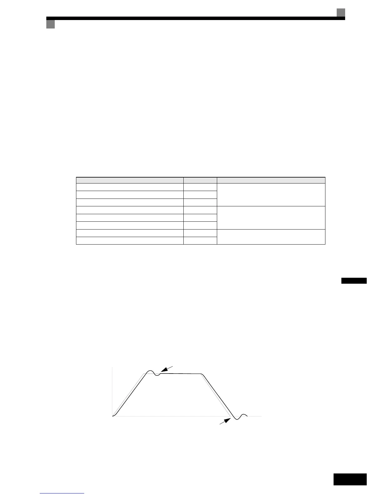
Fig 6.43 Influence of the ASR Gain and Bias
Parameter Setting Explanation
H4-01 Monitor selection (terminal FM) 20
Settings that allow multi-function analog output 1 to be used to
monitor the frequency reference after soft starter.
H4-02 Gain (terminal FM) 100%
H4-03 Bias (terminal FM) 0.0%
H4-04 Monitor selection (terminal AM) 5
Settings that allow multi-function analog output 2 to be used to
monitor the motor speed.
H4-05 Gain (terminal AM) 100%
H4-06 Bias (terminal AM) 0.0%
H4-07 Analog output 1 signal level selection 1
This setting allows a 0 to ± 10 V signal range to be monitored.
H4-08 Analog output 2 signal level selection 1
Time
If undershooting occurs:
Decrease C5-03 and/or increase C5-04
If overshooting occurs:
Decrease C5-01 and/or increase C5-02
Motor speed
 Loading...


