4-4
4
Power ON
Confirm all of the following items and then turn ON the power supply.
• Check that the power supply is of the correct voltage.
200 V class: 3-phase 200 to 240 VDC, 50/60 Hz
400 V class: 3-phase 380 to 480 VDC, 50/60 Hz
• Make sure that the motor output terminals (U, V, W) and the motor are connected correctly.
• Make sure that the Inverter control circuit terminal and the control device are wired correctly.
• Set all Inverter control circuit terminals to OFF.
• When using a PG Speed Control Card, make sure that it is wired correctly.
Checking the Display Status
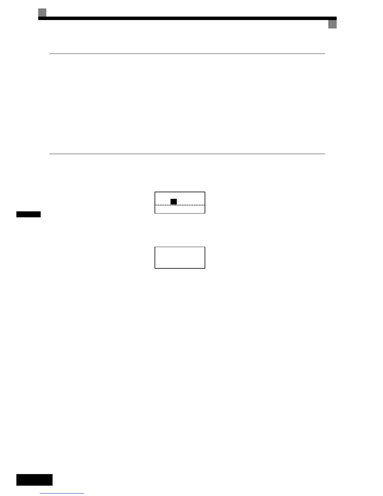
After normal power up without any problems the operator display shows the following:
When a fault has occurred, the details of the fault will be displayed instead of the above display. In that case,
refer to Chapter 7 Troubleshooting. The following display shows an example of a display for faulty operation.
Display for normal operation
The frequency reference monitor is dis-
played in the data display section.
Display for fault operation
The display will differ depending on the
type of fault.
A low voltage alarm is shown at left.
Frequency Ref
-DRIVE-
U1-02=50.00Hz
U1-03=10.05A
Rdy
U1- 01=50.00Hz
-DRIVE-
UV
DC Bus Undervolt
 Loading...


