2-2
2
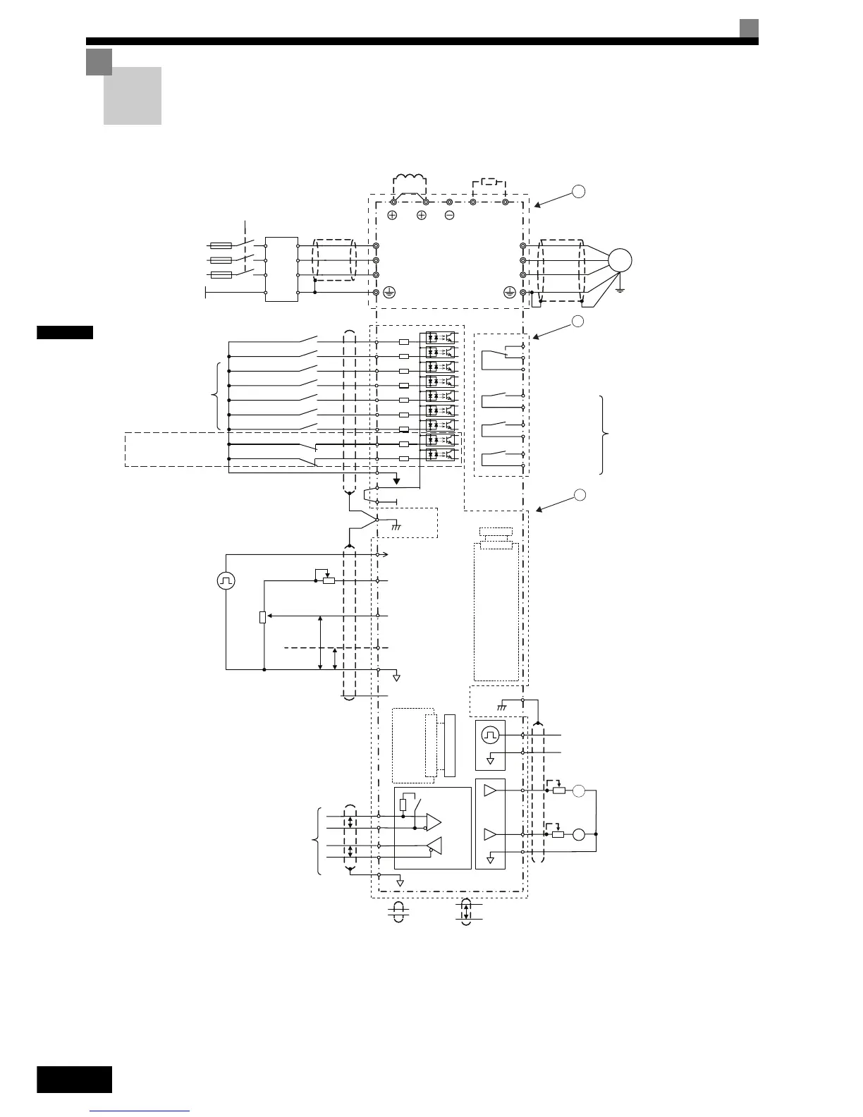
Connection Diagram
The connection diagram of the Inverter is shown in Fig 2.1.
When using the Digital Operator, the motor can be operated by wiring only the main circuits.
Fig 2.1 Connection Diagram (Model CIMR-F7Z47P5 Shown Above)
T
P
+
+
-
-
1
2
3
Terminating
resistance
BB
BB1
IG
MEMOBUS
communication
RS-485/422
P
P
R+
R-
S+
S-
Shielded
wires
Twisted-pair
shielded wires
Analog input setting
adjustment
2 k
Ω
0 to 10 V
2 k
Ω
4 to 20 mA
PP
Pulse train input [Default:
Frequency reference input]
0 to 32 kHz
Analog input power supply
15 V, 20 mA
Analog input 1: Master
frequency reference
0 to 10 V (20 k
Ω)
Multi-function analog input 2
[Default: Frequency bias
4 to 20 mA (20 k
Ω)]
0 V
Analog input power supply
-15 V, 20 mA
RP
+V
A1
A2
AC
-V
FM
AM
AC
AM
FM
AC
MP
Adjustment,
20 k
Ω
Adjustment,
20 k
Ω
Multi-function analog output 2
(-10 to +10 V, 2 mA / 4 to 20 mA)
[Default: Output current, 0 to 10 V)
4 to 20 mA (20 k
Ω)]
Multi-function analog output 1
(-10 to +10 V, 2 mA / 4 to 20 mA)
[Default: Output frequency, 0 to 10 V)
4 to 20 mA (20 k
Ω)]
Pulse train output
0 to 32 kHz (2.20 k
Ω)
[Default: Output frequency]
E(G)
Shield
terminal
Forward Run / Stop
Reverse Run / Stop
External Fault
Fault reset
Multi-step speed setting 1
Multi-step speed setting 2
Jog frequency selection
Multi-function
digital inputs
[Factory setting]
S1
S2
S3
S4
S5
S6
S7
SN
SC
SP
24 V
E(G)
Shield
terminal
MA
MB
MC
M1
M2
M3
M4
M5
M6
Multi-function digital output
250 VAC, 1 A max.
30 VDC, 1 A max.
Fault relay output
250 VAC, 1 A max.
30 VDC, 1 A max.
Relay output 1
[Default: Running]
Relay output 2
[Default: Zero speed]
Relay output 3
[Default:
Frequency agree 1]
DC reactor to improve input
power factor (optional)
Braking resistor unit (optional)
Short-circuit bar
Main Contactor
Fuses
Line
Filter
3-phase power
380 to 480 V
50/60 Hz
L1
L3
L2
PE
T/L3
R/L1
S/L2
W/T3
U/T1
V/T2
B2
B1
1
2
Varispeed F7
M
2CN
PG
Option
Card
2CN
Input
Option
Card
Hardware Baseblock
Hardware Baseblock 1
Hardware Baseblock Terminals
are only available in the Inverter
Version with Safety
 Loading...


